Programmable non-overlapping clock generation circuit and work method thereof

A clock generation circuit, non-overlapping technology, applied in the direction of single pulse train generator, etc., can solve problems such as changing delay, and achieve the effect of expanding the scope of application

Inactive Publication Date: 2013-06-05
SHANDONG UNIV
View PDF7 Cites 2 Cited by
  • Summary
  • Abstract
  • Description
  • Claims
  • Application Information

AI Technical Summary

Problems solved by technology

[0006] However, the non-overlapping clock delay generated by the above existing non-overlapping clock generation circuit is fixed, but in practice, it is expected that the non-overlapping clock generation circuit can change the delay according to the frequency of the input clock signal

Method used


Image

  • Programmable non-overlapping clock generation circuit and work method thereof
  • Programmable non-overlapping clock generation circuit and work method thereof
  • Programmable non-overlapping clock generation circuit and work method thereof

Examples


Embodiment 1

[0048] Such as Image 6 , 7 , 8 shown.

[0049] A programmable non-overlapping clock generation circuit, comprising two signal branches and an inverting module 3, branch A in the two signal branches, comprising a logic module 11, a delay module 12 and a series connection Select the control module 13, the selection control module 13 is connected to the signal output terminal clka; the branch B in the two signal branches includes a logic module 21, a delay module 22 and a selection control module 23 connected in series, the The selection control module 23 is connected to the signal output terminal clkb; the signal input terminal clk is connected to the input terminal of the inverting module 3 and an input terminal of the logic module 11, and the other input terminal of the logic module 11 is connected to the signal output terminal clkb ; The output terminal of the inverting module 3 is connected to an input terminal of the logic module 21, and the other input terminal of the l...

Embodiment 2

[0063] A working method of a programmable non-overlapping clock generating circuit as described in Embodiment 1, comprising the steps as follows:

[0064] 1) The signal is input to the programmable non-overlapping clock generation circuit along the signal input terminal clk;

[0065] 2) In the delay programmable control module 132, by encoding the control bit of the feedback point selection module 131: select the i1th series node in the delay module to connect with the input terminal on the feedback point selection module 131, where i1 is greater than or equal to 1 and an integer less than or equal to n, then the total delay of the signal in branch A is i1×T;

[0066] In the delay programmable control module 232, by coding the control bit of the feedback point selection module 231: select the i2th series node in the delay module to communicate with the input on the feedback point selection module 231, wherein i2 is greater than or equal to 1 and less than is an integer equal ...

Embodiment 3

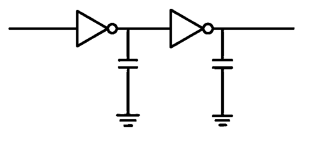
[0072] The circuit described in Embodiment 1 is different in that the delay unit includes two inverters connected in series, and the output terminal of each inverter is respectively connected to a capacitor and grounded. Such as image 3 shown.


PUM


Abstract

The invention relates to a programmable non-overlapping clock generation circuit. The programmable non-overlapping clock generation circuit comprises two signal branches and an anti-phase module (3), wherein a branch A of the two signal branches comprises a logical module (11), a delaying module (12) and a selective control module (13) which are connected in series, the selective control module (13) is connected with a signal output end clka, a branch B of the two signal branches comprises a logical module (21), a delaying module (22) and a selective control module (23) which are connected in series, and the selective control module (23) is connected with a signal output end clkb. The programmable non-overlapping clock generation circuit changes the structure of an existing non-overlapping clock generation circuit, enables the structure of the existing non-overlapping clock generation circuit to generate non-stationary non-overlapping clock delaying, changes the delaying according to the different frequencies of input clock signals, and widens the application range.

Description

technical field [0001] The invention relates to a programmable non-overlapping clock generation circuit and its working method, belonging to the technical field of clock signal generation circuits. Background technique [0002] Non-overlapping clocks are often used in circuits such as switched capacitor circuits and charge pumps. The non-overlapping clock circuit generates non-overlapping clocks, the control node is not driven by two voltages at the same time, and a clock that is turned off in advance is generated to reduce the impact of the charge injection effect. figure 1 It is a timing diagram of non-overlapping clocks. The rising edge of b occurs after the falling edge of a reaches t1, and the rising edge of a occurs after the falling edge of b reaches t2. There is no high level during the positive pulse width of both a and b. Overlapping area, where t1, t2 are non-overlapping time. The delay is generated by the buffer module, and there are many ways to implement the ...

Claims


Application Information

Patent Timeline
IPC IPC(8): H03K3/78
Inventor 周莉潘芦苇孙涛陈鹏高园园
Owner SHANDONG UNIV
Why Eureka
Try Eureka