Control device for internal combustion engine

A technology for a control device and an internal combustion engine, applied in engine control, internal combustion piston engine, electrical control, etc., can solve problems such as catalyst surface area reduction and catalyst degradation, and achieve the effects of improving acceleration responsiveness, inhibiting degradation, and reducing heat gain.

Inactive Publication Date: 2013-05-22
TOYOTA JIDOSHA KK
View PDF5 Cites 6 Cited by
  • Summary
  • Abstract
  • Description
  • Claims
  • Application Information

AI Technical Summary

Problems solved by technology

[0005] In addition, when the temperature of the catalyst is high in an oxygen-excess state such as when fuel supply is stopped, sintering develops and the surface area of ​​the catalyst decreases, thereby possibly accelerating the deterioration of the catalyst.
Therefore, in the above-mentioned internal combustion engine equipped with a turbocharger, when the temperature of the turbocharger is high and the oil supply is stopped when the deceleration is performed, there is a concern that the deterioration of the catalyst will be accelerated.

Method used


Image

  • Control device for internal combustion engine
  • Control device for internal combustion engine
  • Control device for internal combustion engine

Examples


Embodiment approach 1

[0042] [System Configuration of Embodiment 1]

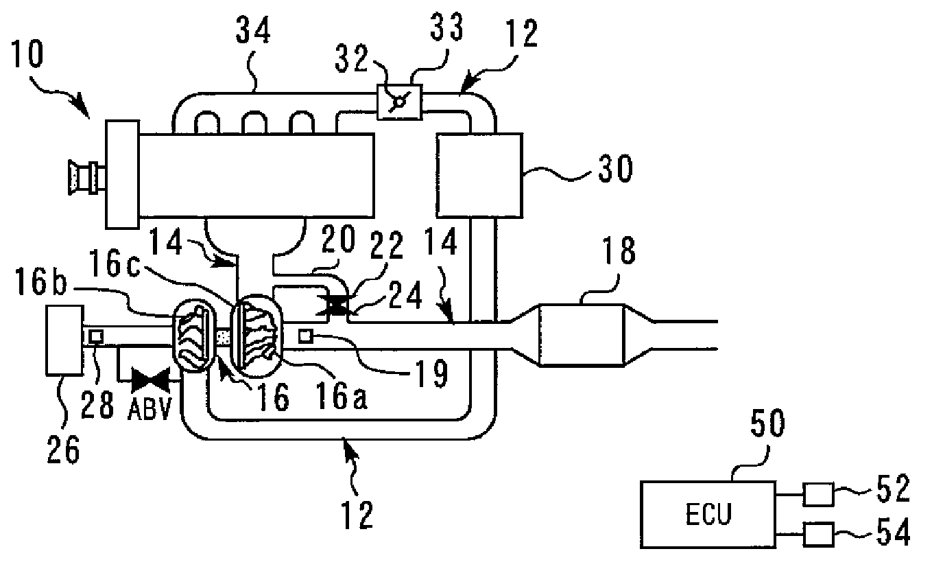
[0043] figure 1 It is a figure for demonstrating the system structure of Embodiment 1 of this invention. figure 1 The system shown has an internal combustion engine 10 . The internal combustion engine 10 is mounted on a vehicle and serves as a power source of the vehicle. figure 1 The illustrated internal combustion engine 10 has more than one cylinder.

[0044] An intake passage 12 and an exhaust passage 14 are connected to each cylinder of the internal combustion engine 10 . An intake valve (not shown) that opens and closes between the inside of the cylinder and the intake passage 12 is provided at the downstream end of the intake passage 12 . Similarly, an exhaust valve (not shown) that opens and closes between the inside of the cylinder and the exhaust passage 14 is provided at an upstream end of the exhaust passage 14 .

[0045] Exhaust gas discharged from each cylinder of the internal combustion engine 10 flows into an...

Embodiment approach 2

[0078] [System Configuration of Embodiment 2]

[0079] Next, refer to Figure 4 Embodiment 2 of the present invention will be described. The system of this embodiment adopts the figure 1 In the structure shown, ECU50 implements the following Figure 4 program to achieve.

[0080] [Characteristic Control in Embodiment 2]

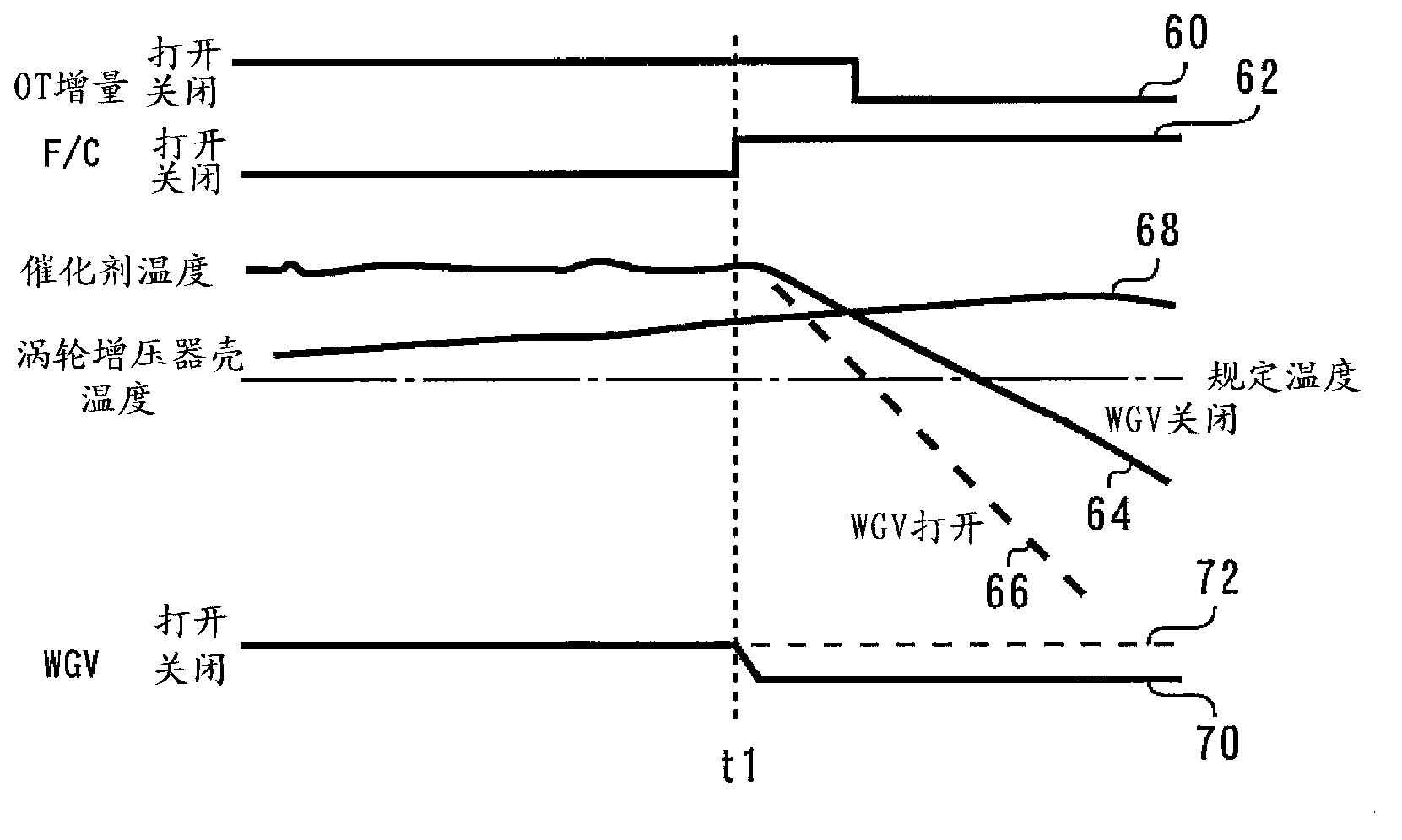
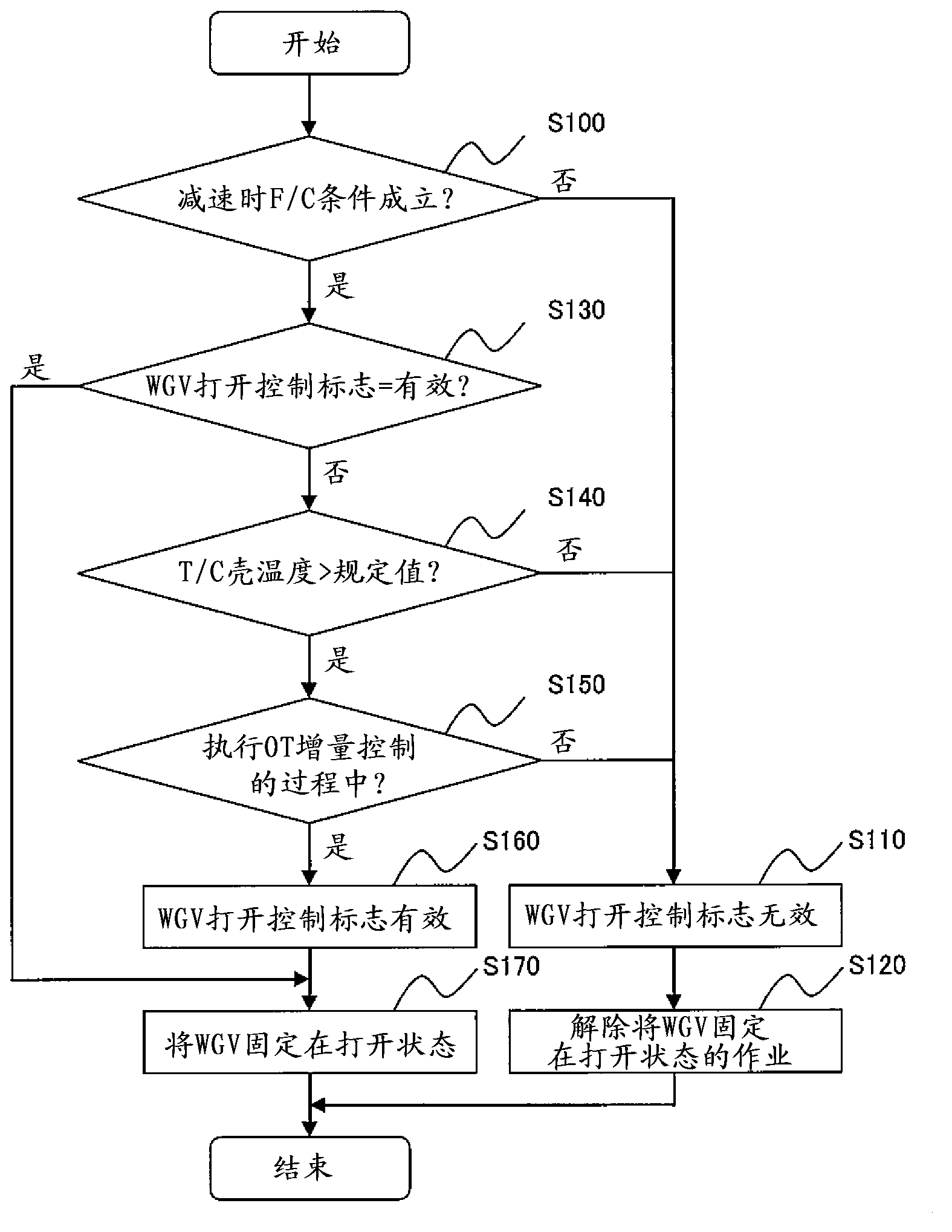
[0081] In Embodiment 1 described above, when the deceleration stop is performed, the wastegate valve 22 is fixed in the open state under predetermined conditions, thereby suppressing the deterioration of the catalyst 18 . However, after passing image 3 In the case where the shown control routine fixes the wastegate valve 22 in the open state, there may be cases where the driver depresses the accelerator to cause an acceleration request. In this case, good acceleration responsiveness is required. On the other hand, there are cases where the temperature of the scroll case is not a high temperature. Therefore, it is desired to be able to suppress the te...


PUM


Abstract

The objective of this invention is to provide a control device for an internal combustion engine capable of suppressing deterioration of the catalyst in an internal combustion engine equipped with a turbocharger when the turbocharger is at a high temperature and when the speed is reduced and the fuel is cut. The internal combustion engine is equipped with: a turbocharger turbine provided in the exhaust passage of the internal combustion engine; a catalyst provided in the exhaust passage farther downstream than the turbine; a bypass passage that bypasses the turbine by connecting the exhaust passage farther upstream from the turbine and the portion of the exhaust passage from the turbine to the catalyst; and a wastegate valve capable of opening / closing the bypass passage. The wastegate valve is opened when the speed is reduced and an operation to cut the fuel is executed, and when the temperature of the turbocharger is higher than a set value.

Description

technical field [0001] The present invention relates to a control device for an internal combustion engine, and in particular, to a control device for an internal combustion engine suitable for controlling an internal combustion engine mounted on a vehicle. Background technique [0002] Conventionally, as disclosed in Patent Document 1 (Japanese Unexamined Patent Publication No. 2009-228486 ), for example, a control device for an internal combustion engine is known, which includes a bypass for communicating upstream and downstream of a turbine of a turbocharger provided in an exhaust passage. a bypass passage; a wastegate valve provided in the bypass passage; and a catalyst provided downstream of a connection portion of the bypass passage in the exhaust passage. In this conventional control device, the normally closed control that closes the wastegate valve in a low-speed rotation and low load region including idling and the normally open control that opens the wastegate val...

Claims


Application Information

Patent Timeline
IPC IPC(8): F02D23/00F01N3/20F02B33/00F02B37/16F02D17/02F02D43/00
CPCF02D41/0007F02B37/18F01N3/10F02D17/02Y02T10/144F02D41/0235F02D2041/0265F02D41/123Y02T10/12
Inventor 大塚孝之
Owner TOYOTA JIDOSHA KK
Why Eureka
Try Eureka