Superconductive current lead welding method

A technology of wire welding and superconducting current, applied in welding equipment, metal processing equipment, manufacturing tools, etc., can solve problems such as loosening and brazing melting, and achieve the effects of reducing the chance of heating, easy operation, and low temperature

Inactive Publication Date: 2007-06-20
INST OF ELECTRICAL ENG CHINESE ACAD OF SCI
View PDF0 Cites 2 Cited by
  • Summary
  • Abstract
  • Description
  • Claims
  • Application Information

AI Technical Summary

Problems solved by technology

Therefore, when using the above-mentioned traditional method to connect the lower end of the high-temperature superconductor and the superconducting magnet, it is easy to cause the re-melting and loosening of the brazing in the first step, and the superconductor is heated to the temperature of tin brazing again.

Method used


Image

  • Superconductive current lead welding method

Examples


Embodiment Construction

[0013] The present invention will be further described below in conjunction with the accompanying drawings and specific embodiments.

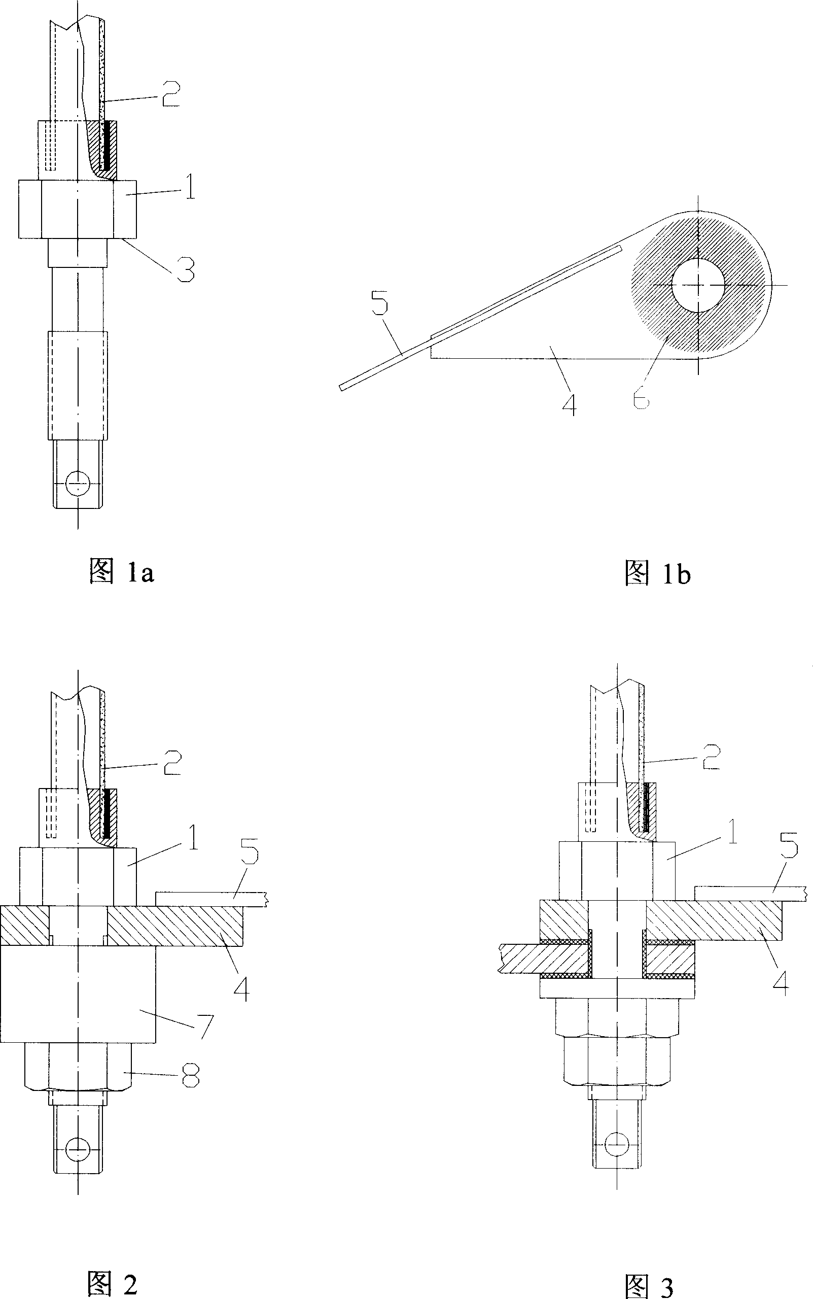
[0014] As shown in FIG. 1 a , the copper pillar 1 is first soldered to the tubular high-temperature superconductor 2 by tin brazing, and at the same time solder is hung on the plane 3 of the copper pillar 1 . As shown in Figure 1b, the copper block 4 is first soldered to the lead-out wire 5 of the superconducting magnet with tin brazing. , which is the shaded area shown in Figure 1b, quickly wipe over to remove excess solder on this area.

[0015] In Fig. 2, the copper pillar 1 and the high-temperature superconductor 2 that have been welded together are put on a lathe to turn the solder layer on the plane 3 until only a thin layer of solder is left on the plane 3, and the thickness of the solder layer is equal to that on the plane 3. The color of copper is not exposed. After using a file to scrape off the excess solder on the edge of the roun...


PUM


Abstract

A method for welding the leading superconductor wire includes such steps as soldering a superconductor onto a transition copper block while applying a thin tin layer to another surface of said copper block to be soldered and soldering between two transition copper blocks by use of the solder with low smelting point.

Description

technical field [0001] The invention relates to a welding method between superconducting wires in current leads of cryogenic devices. Background technique [0002] The most primitive current lead in cryogenic devices is a piece of structure, made of copper or alloy materials. After the emergence of high-temperature superconductors, in order to reduce the heat leakage of the current leads, the current leads are changed to a two-stage structure, especially for the case of supplying power to superconducting magnets (or samples) in the extremely low temperature region. In the two-stage structure, the section above the liquid nitrogen temperature zone is still made of copper or alloy materials, and the section below the liquid nitrogen temperature zone is a tubular, rod-shaped or strip-shaped high-temperature superconductor. [0003] Since the current carried by the superconducting current lead is generally relatively large, in order to reduce the joint resistance or consider th...

Claims


Application Information

Patent Timeline
IPC IPC(8): B23K1/19B23K1/20
Inventor 雷沅忠赵保志戴银明宋守森王秋良
Owner INST OF ELECTRICAL ENG CHINESE ACAD OF SCI
Why Eureka
Try Eureka