
Insulation tube bus and manufacturing method thereof

An insulating tube and busbar technology, which is used in the manufacture of insulated cables, insulated conductors, and cables/conductors. Safe and reliable, high product qualification rate

Inactive Publication Date: 2013-05-22
孙闻峰
View PDF6 Cites 13 Cited by
  • Summary
  • Abstract
  • Description
  • Claims
  • Application Information

AI Technical Summary

Problems solved by technology

Due to the very low friction coefficient of PTFE (only 0.15) and the lubricating effect of silicone oil, it is very easy to cause insulation slippage and slippage of the capacitive screen during production and handling; as PTFE is extremely difficult to bond, the product is not easy to Sealing, coupled with the excellent ductility of silicone oil and thermal expansion and contraction, oil leakage occurs from time to time during transportation and operation, and it is impossible to replenish oil for maintenance; the joint must be constructed on site, and cannot be carried out in bad weather; Due to its manufacturing process, it is easy to cause interface air gap and moisture absorption, so the partial discharge and dielectric loss performance often exceed the standard, resulting in breakdown accidents; the mechanical strength is low, and it needs to be supported by post insulators to bear the load during operation.

Method used


Image

  • Insulation tube bus and manufacturing method thereof
  • Insulation tube bus and manufacturing method thereof
  • Insulation tube bus and manufacturing method thereof

Examples


Embodiment Construction

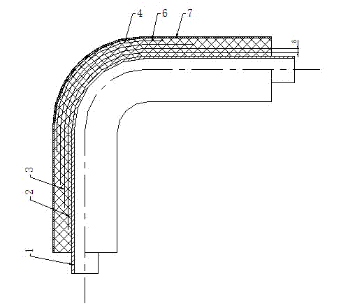
[0028] Figure 1a with Figure 1b What is shown in the figure is an insulating tube busbar, which consists of a conductive tube 1, an insulating layer 2, a voltage equalizing screen 3, an outer shielding layer 4, a grounding wire 5, an insulating outer protective layer 6, and an anti-aging layer 7, wherein the insulating layer 2 Made of glass fiber roving with figure 2 or glass fiber cloth with image 3 The intercrossing and lapping winding methods shown in the above are uniformly wound to the design size; the equalizing screen 3 is made of aluminum foil, wire mesh, ribbon or tow-shaped conductive carbon fiber or semiconductor material figure 2 The method shown is evenly wound to the required size; and after the voltage equalizing screen 3 and the insulating layer 2 are alternately wound to the required size, the outer shielding layer 4 is wound on it, and the grounding wire 5 is embedded in the set position of the outer shielding layer; The shielding layer is wrapped with...


PUM


Abstract

The invention relates to a material technology and a method for manufacturing an insulation tube bus. The insulation tube bus is composed of an electric conduction tube, an insulating layer, a pressure equalizing screen, an external shielding layer, a ground lead, an insulating external protection layer and an ageing resistance layer, wherein the electric conduction tube is manufactured from an aluminum tube or a copper tube, the insulating layer is wound on the electric conduction tube through glass fiber dipping insulating glue and reaches a needed size, the pressure equalizing screen is formed by evenly twining banding or filament bundle conductor or semiconductor materials, the external shielding layer is wound on the pressure equalizing screen and the insulating layer after the pressure equalizing screen and the insulating layer are alternately twined to needed sizes, the ground lead is pre-buried in a set position of the external shielding layer, the insulating external protection layer is wound on the exterior of the external shielding layer, solidification is performed under set temperature and time, and finally the ageing resistance layer is manufactured on the surface of the insulating external protection layer. The insulation tube bus manufactured by using the method has the advantages of being high in mechanical strength, good in heat dispersion, low in magnitude of partial discharge, high in product percent of pass, low in manufacturing cost, short in production cycle, convenient to construct on site, safe and reliable in running, maintenance-free and the like.

Description

technical field [0001] The present invention relates to a busbar with shielding insulating tube used in high-voltage electrical equipment in a power system and a manufacturing method thereof. Specifically, the present invention relates to a capacitive main insulating structure for improving field strength along the surface and having an insulating effect on ground and its production method. [0002] Background technique [0003] At present, there is a manufacturing technology of insulating film coated with insulating oil. The internal insulation of the insulating pipe bus produced by this technology is rolled by insulating film and aluminum foil coated with insulating oil. The manufacturing method is: along the axial direction of the pipe bus Aluminum foil and polytetrafluoroethylene film are alternately wrapped to form a uniform pressure layer, and silicone oil is applied between the polytetrafluoroethylene films and between the aluminum foil and the polytetrafluoroethylen...

Claims


Application Information

Patent Timeline
Patent Type & Authority Applications(China)
IPC IPC(8): H01B7/02H01B7/17H01B7/28H01B13/00
CPCY02A30/14
Inventor 孙闻峰
Owner 孙闻峰
Learn More