
Steam blasting machine

A technology of steam explosion machine and warehouse explosion, which is applied in chemical instruments and methods, methods of chemically changing substances by using atmospheric pressure, chemical/physical processes, etc., can solve the problem of reducing energy density, increasing equipment costs, and large loss of sealing rings. and other problems, to achieve the effect of uniform heating and pressure, speeding up the explosion speed, and high work efficiency

Active Publication Date: 2015-01-21
SICHUAN TUOPAI SHEDE WINE
View PDF5 Cites 2 Cited by
  • Summary
  • Abstract
  • Description
  • Claims
  • Application Information

AI Technical Summary

Problems solved by technology

However, in fact, the existing steam explosion devices in use cannot meet the requirements of technical performance, and can only be called thermal spray devices. The basic mode is: a valve is installed at the bottom of a pressure vessel, and the valve is quickly opened To realize the sudden release of pressure in the container, resulting in a thermal spray effect
The main problem of this mode is: because the venting section of the valve is much smaller than the volume section of the pressure vessel, and the opening speed of the high-pressure valve is limited, the pressure release process of the high-pressure steam in the vessel takes a long time, generally 3-10 seconds, far The release cannot reach the millisecond level, so it is impossible to realize steam adiabatic expansion and work, which reduces the energy density and makes the material decomposition degree not high
However, although this invention belongs to the principle of sliding cover, in fact, the upper part of the explosion chamber adopts sliding sealing, and the lower part still adopts the principle of end face sealing, which leads to a very large loss of sealing ring, and the sealing ring needs to be replaced frequently, which affects work efficiency. ;Adopt the way of feeding in the middle of the upper sliding sealing cover, and the feeding port adopts suspension sealing, which requires a separate cylinder to provide power, which not only complicates the device but also increases the equipment cost
[0007] Specifically, the steam explosion machine with this structure mainly has the following problems: first, the lower end face is sealed, resulting in a great loss of the sealing ring; The connection constitutes a sliding cover, which makes the entire sliding cover a "squirrel cage" structure, and additionally needs to add a sealing device for the feeding port; the existing suspension sealing device or thread seal, the raw material directly enters the explosion chamber from the feeding port. After the warehouse, when the sliding cover moves downward to open the port seal, the material is delayed or hindered by the multi-pillar resistance of the "squirrel cage" structure of the sliding cover, and the explosive material will accumulate in the On the chassis of the sliding sealing cover, in the state of continuous steam explosion of the numerical control, the explosive materials accumulated on the chassis of the sliding sealing cover will burn into hard lumps after many rounds of steam explosion, especially in the steam explosion starchy When making raw materials, due to the viscosity of the material, it will also adhere to the pillars of the "squirrel cage" structure and the chassis of the sliding sealing cover, and all of them will be coked into hard lumps, which will seriously affect the quality of the explosive material and the continuous working state of the steam explosion machine. confirmed by experiment

Method used


Image

  • Steam blasting machine
  • Steam blasting machine
  • Steam blasting machine

Examples


Embodiment

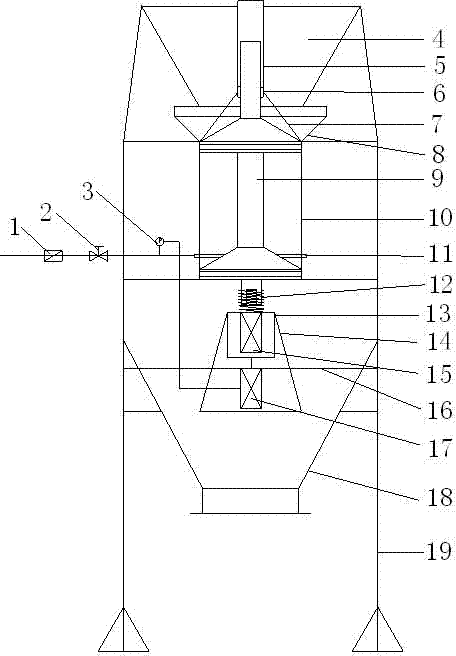
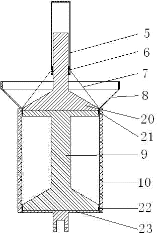
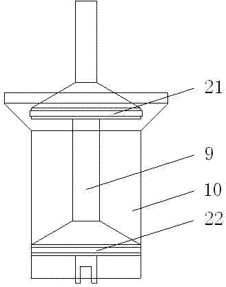
[0031] Such as Figure 1-4 Shown, the concrete structure of steam explosion machine of the present invention is as follows:

[0032]It includes feed hopper 4, receiving hopper 8, discharge hopper 18, burst chamber 10, sliding sealing disc 9, upper limit shaft 20, lower sealing disc 23, upper sealing ring 21, lower sealing ring 22, cylinder A15, cylinder B17 and Frame 19, described feeding hopper 4 is the conical shape of up big and down small, and its below connects conical receiving hopper 8, and the below of receiving hopper 8 connects blasting bin 10, and discharging hopper 18 is located at the below of blasting bin 10, The discharge hopper is connected with the frame, and the frame 19 supports the discharge hopper 18, and the discharge hopper will collect all the materials that burst into bags.

[0033] Among them: the upper limit shaft is set on the top of the sliding sealing plate and is located in the receiving hopper, which is used to limit the upward movement of the ...


PUM


Abstract

The invention discloses a steam blasting machine which comprises a sliding sealing disc, a movable upper limiting shaft, a lower sealing disc, an upper sealing ring, a lower sealing ring, a cylinder A for controlling the sliding sealing disc to move upwards and a cylinder B for controlling the sliding sealing disc to move downwards, wherein the sliding sealing disc is I-shaped; the lower part of the sliding sealing disc is in a conical disc structure having a high middle part and a low peripheral part; the lower end of the upper limiting shaft is matched with the upper end of the sliding sealing disc in a sealing manner through the upper sealing ring so as to form an integrated structure; the lower end of the sliding sealing disc is matched with the lower sealing disc in the sealing manner through the lower sealing ring so as to form another integrated structure; the sliding sealing disc is sealed in a sliding manner through the upper sealing ring and the lower sealing ring which slide up and down in a blasting bin; the cylinder A is connected with the bottom of the lower sealing disc; and the cylinder B is connected below the cylinder A. The steam blasting machine is simple in structure and high in working efficiency and can finish the supersonic steam blasting crush in milliseconds; materials are fed and blasted out more rapidly in the steam blasting process. In addition, the raw material accumulation and the material residues are avoided.

Description

Technical field [0001] The present invention involves a steam explosion, especially a steam explosion device for steam explosion and cooked steaming and cooked processing of starch, protein and other raw materials for biomass. Background technique [0002] The steam explosion technology has been more than 90 years since the 1920s. From the beginning of the production of artificial fiber boards, extracting ethanol, slurry paper, and animal feed in the food industry, the pharmaceutical industry, and the pharmaceutical industry,The application prospects and technical advantages of biological energy, materials, chemistry and environmental protection have become increasingly prominent. [0003] The full name of the steam technology is "steam blasting technology". The technical principle is: the steam molecules inside the biomass tissue have emerged in a short time, and the raw materials are decomposed by less energy according to less energy.The explosion machine is a mechanical device...

Claims


Application Information

Patent Timeline
Patent Type & Authority Patents(China)
IPC IPC(8): B01J3/00
Inventor 李家民
Owner SICHUAN TUOPAI SHEDE WINE
Learn More