
Full-integration complementary metal oxide semiconductor (CMOS) super-regeneration time division multiplexing wireless receiver structure

A wireless receiver, time-division multiplexing technology, applied in the field of short-distance wireless super-regenerative receiver system architecture

Inactive Publication Date: 2013-05-15
南京矽志微电子有限公司
View PDF3 Cites 16 Cited by
  • Summary
  • Abstract
  • Description
  • Claims
  • Application Information

AI Technical Summary

Problems solved by technology

But there is a contradiction between obtaining a stable starting state and improving the receiving sensitivity

Method used


Image

  • Full-integration complementary metal oxide semiconductor (CMOS) super-regeneration time division multiplexing wireless receiver structure
  • Full-integration complementary metal oxide semiconductor (CMOS) super-regeneration time division multiplexing wireless receiver structure
  • Full-integration complementary metal oxide semiconductor (CMOS) super-regeneration time division multiplexing wireless receiver structure

Examples


Embodiment Construction

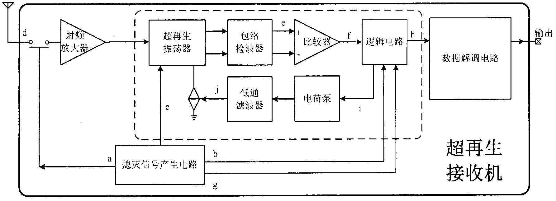
[0016] Super regenerative receiver structure of the present invention such as figure 2 shown. The receiver works in a different way, and realizes the functions and performances required by the system through multiple module circuits. Including: RF amplifier, SRO with loop control function (including SRO, envelope detection circuit, comparator, logic circuit, charge pump, low-pass filter), extinguishing signal generation circuit and data demodulation circuit.

[0017] The specific circuit module realization of super regenerative receiver of the present invention will be discussed below:

[0018] 1. Design of RF Amplifier

[0019] Invented RF amplifiers such as Figure 4 shown. The circuit adopts a classic cascode structure, which has the advantages of high upper frequency limit and high reverse isolation.

[0020] Compared with the traditional active inductance, the active inductance designed by the present invention has one more resistance Rd, such as Figure 4 shown in...


PUM


Abstract

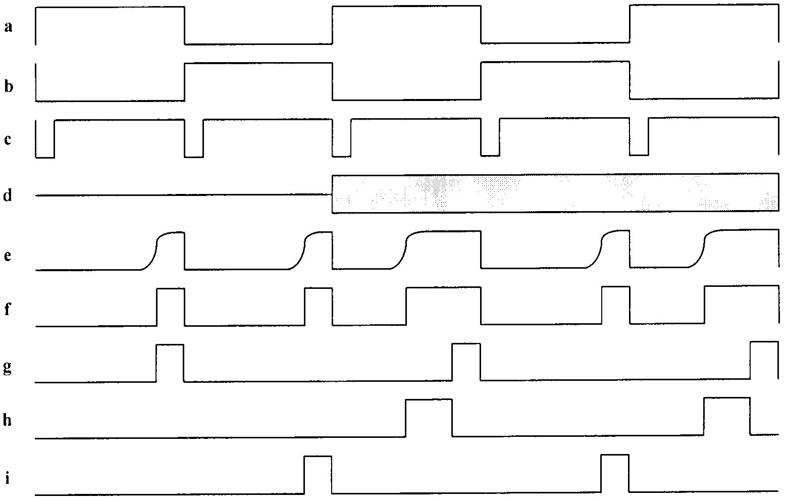
The invention discloses a full-integration complementary metal oxide semiconductor (CMOS) super-regeneration time division multiplexing wireless receiver structure in an analog integrated circuit. A control mode of time division multiplexing is adopted in the receiver, and the contradiction between stabilizing of oscillation-starting time and improving of receiving sensitivity is solved. Basic building modules of the wireless receiver structure comprise a radio frequency amplifier, a singly resonant oscillator (SRO) with the function of loop control, a black out signal producing circuit and a data demodulator circuit, wherein the SRO with the function of loop control comprises a SRO, an envelope detection circuit, a comparator, a logic circuit, a charge pump and a low pass filter. A super-regeneration oscillator works in an interrupted oscillation state, and the interrupted oscillation period of the super-regeneration oscillator is controlled by black out signals, but the oscillation-starting time in each oscillation period is mainly determined by input signals amplified through a low noise amplifier (LNA). When the frequency of the input signals is in accordance with the frequency of the oscillator, or the frequency of the input signals is higher in strength, the oscillation-starting time of the oscillator is shortened, otherwise the oscillation-starting time is increased, and the oscillation-starting time which changes along with the changes of the frequency or the strength of the input signals is the basis for distinguishing input signal logic by the super-regeneration receiver. After envelope detection, the change of the oscillation-starting time is translated into the change of pulse widths, and pulses pass through the data demodulator circuit to obtain output data. In order to reduce the influence on the receiving sensitivity by noise generated by a control clock to the greatest extent, a multi-circuit control clock and the black out signal producing circuit are integrated in the receiver, and therefore the whole receiver works in a synchronous-clock mode.

Description

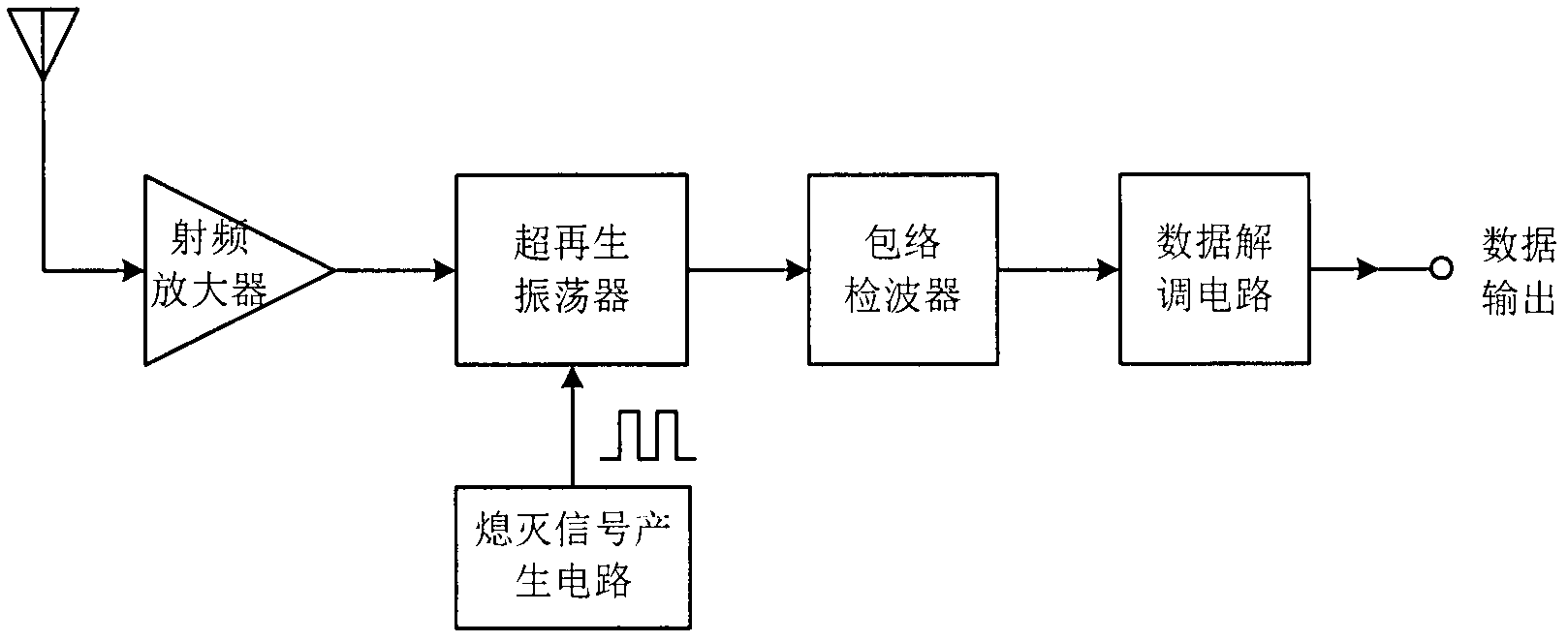
technical field [0001] The invention relates to a short-distance wireless super-regenerative receiver system architecture in the communication field. Background technique [0002] Due to the advantages of simple structure, low power consumption, and low cost, wireless receivers based on super-regenerative theory are very suitable for short-distance wireless communication systems such as wireless sensor networks, home automatic control, and anti-theft. [0003] figure 1 It is a typical super regenerative receiver, including radio frequency amplifier, super regenerative oscillator (SRO), extinguishing signal generation circuit, envelope detection circuit and demodulation circuit, etc. The super regenerative oscillator works in the intermittent oscillation state, and its intermittent oscillation cycle is controlled by the off signal, but the start-up time in each oscillation cycle is mainly determined by the input signal amplified by the low noise amplifier. When the frequenc...

Claims


Application Information

Patent Timeline
Patent Type & Authority Applications(China)
IPC IPC(8): H04B1/16H04J3/02
Inventor 王欢徐建罗寅管志强王蓉曾贤文王志功
Owner 南京矽志微电子有限公司
Learn More