
Programmable gain amplifier

A programming gain and amplifier technology, applied in the direction of gain control, amplification control, electrical components, etc., can solve the problem of inaccurate resistance ratio, adverse effects of programmable gain amplifier feedback loop stability, and inaccurate gain of programmable gain amplifier and other problems, to achieve the effect of precise control of gain, easy promotion and application, and simple structure

Active Publication Date: 2013-05-15
SHANGHAI INTEGRATED CIRCUIT RES & DEV CENT
View PDF3 Cites 13 Cited by
  • Summary
  • Abstract
  • Description
  • Claims
  • Application Information

AI Technical Summary

Problems solved by technology

The on-resistance of the MOS switch will cause the resistance ratio of the feedback resistance of the programmable gain amplifier to the input resistance to be inaccurate, resulting in inaccurate gain of the programmable gain amplifier.
In traditional programmable gain amplifiers, in order to overcome this defect, the area of ​​the MOS switch is usually made larger to reduce the on-resistance, but it also causes parasitic capacitance, which will be detrimental to the stability of the feedback loop of the programmable gain amplifier. influences

Method used


Image

  • Programmable gain amplifier
  • Programmable gain amplifier
  • Programmable gain amplifier

Examples


Embodiment Construction

[0016] The specific embodiment of the present invention will be further described in detail below in conjunction with the accompanying drawings.

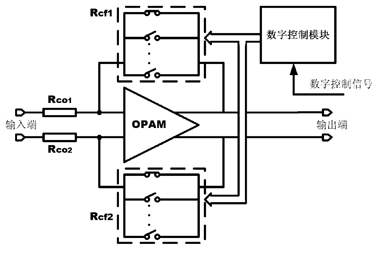
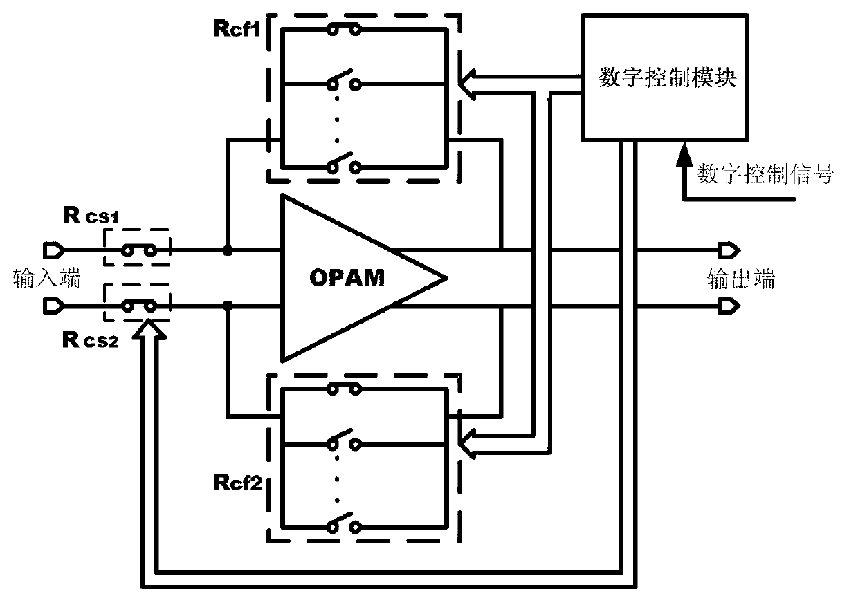
[0017] Such as figure 1 As shown, the programmable gain amplifier of an embodiment of the present invention includes: an operational amplifier OPAM, two first CMOS switch arrays Rcf1 and Rcf2, and a digital control module.

[0018] Among them, the operational amplifier has differential input and differential output, that is, it has a pair of differential input terminals and a pair of differential output terminals, and its two input terminals are respectively connected in series with a resistance unit Rco1 and Rco2, and are used as the input terminal of the programmable gain amplifier. The resistance value of the resistance unit is constant, and the operational amplifier OPAM is used to amplify the input signal of the gain amplifier and finally output it; the two first CMOS switch arrays Rcf1 and Rcf2 are both composed of a plurality...


PUM


Abstract

The invention relates to a programmable gain amplifier. The programmable gain amplifier comprises an operational amplifier, at least one first complementary metal oxide semiconductor (CMOS) switch array, and a digital control module, wherein the operational amplifier comprises two input ends and at least one output end, at least one input end is in tandem connection with a resistor unit, the operational amplifier is used for amplifying and outputting output signals of the gain amplifier, the first CMOS switch array is composed of a plurality of CMOS switches which are in parallel connection with each other, the first CMOS switch array is connected between one input end and one output end of the operation amplifier in a bridging mode, and the digital control module is used for controlling on-off of all CMOS switches according to digital control signals so as to adjust the first CMOS switch array. The programmable gain amplifier realizes accurate regulation of gain, and is favorable to reducing stray capacitance.

Description

technical field [0001] The present invention relates to wireless communication systems, and more particularly, to a programmable gain amplifier. Background technique [0002] In a wireless communication system, the signal strength received by the receiver will change with the distance between the receiver and the transmitter or obstacles and other factors. In order for the receiver to maintain a relatively stable output signal amplitude under different input signal strengths, it is necessary to set a gain adjustment function in the receiving chain. When the signal is strong, the receiver gain is reduced, and when the signal is weak, the gain is increased. . A programmable gain amplifier needs to have a large gain adjustment range. In most cases, multi-stage programmable gain amplifiers with lower maximum gain are required to be cascaded to obtain a larger gain adjustment range. [0003] A traditional programmable gain amplifier needs to change the ratio of its feedback re...

Claims


Application Information

Patent Timeline
IPC IPC(8): H03G3/30
Inventor 孙翔董林妹方泽姣
Owner SHANGHAI INTEGRATED CIRCUIT RES & DEV CENT
Learn More