A method and system for treating acid gas

A technology of acidic gas and gas, applied in separation methods, chemical instruments and methods, and separation of dispersed particles, can solve the problems of high sewage treatment costs, high one-time investment costs, and rising treatment costs, and achieve neutralization Effects of capacity improvement, energy consumption reduction, and capacity enhancement

Inactive Publication Date: 2015-08-12
ZHEJIANG YUHUI SOLAR ENERGY SOURCE
View PDF4 Cites 0 Cited by
  • Summary
  • Abstract
  • Description
  • Claims
  • Application Information

AI Technical Summary

Problems solved by technology

However, the operation of the evaporation system consumes a lot of energy, which greatly increases the treatment cost, and the cost of one-time investment is high, so that the current sewage treatment cost remains high.

Method used


Image

  • A method and system for treating acid gas
  • A method and system for treating acid gas
  • A method and system for treating acid gas

Examples


specific Embodiment 1

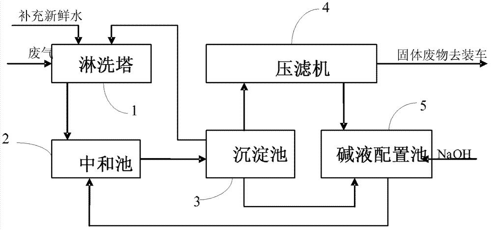
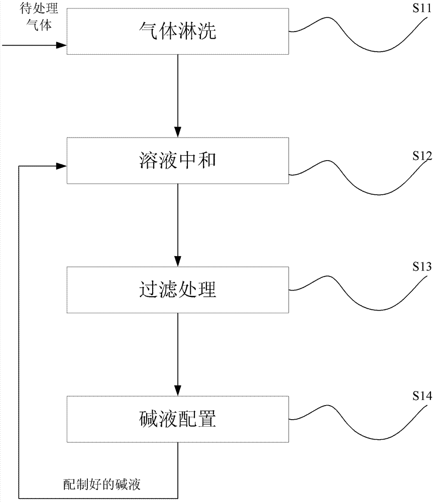
[0028] Please refer to the attached figure 1 And attached image 3 , with figure 1 It is the flow chart of the specific embodiment 1 of the acid gas treatment method disclosed in the present invention, wherein the labels 1-5 are respectively the leaching tower, the neutralization tank, the sedimentation tank, the filter press, the lye configuration tank, and the attached image 3 It is a flowchart of the acid gas treatment method disclosed in the present invention, including steps:

[0029] S11: gas leaching;

[0030] The waste gas produced in the polysilicon production process is passed into the leaching tower for gas rinsing. The leaching tower adopts the countercurrent operation of gas and liquid so that the gas can be fully absorbed. During this stage, HCl is absorbed into the liquid phase and the chlorosilane component reacts with water to form SiO 2 and HCl, into the wastewater system. Wherein the reaction equation of chlorosilane is:

[0031] SiHCl 3 +3H 2 O=H2S...

specific Embodiment 2

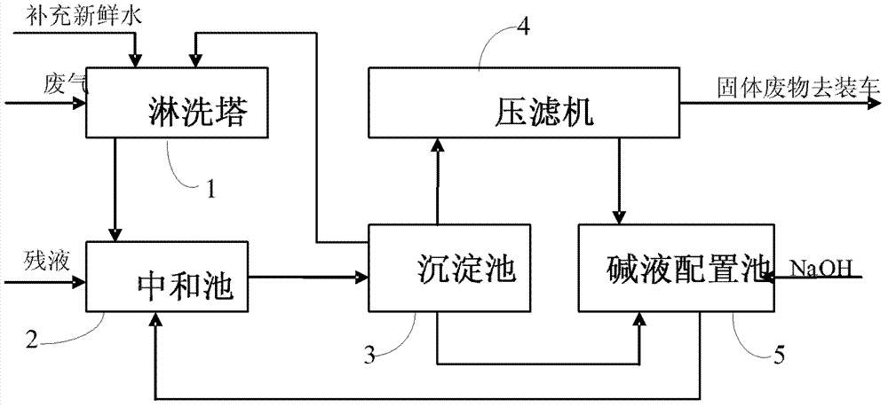
[0046] The present invention also includes another specific implementation mode, please refer to the attached figure 2 And attached image 3 , with figure 2 It is the specific flow chart of the present embodiment, and the labels 1-5 are respectively the leaching tower, the neutralization tank, the sedimentation tank, the filter press, the lye configuration pool, and the attached image 3 It is a flowchart of the method of the present invention. Include steps:

[0047] S11: gas leaching;

[0048] The waste gas produced in the polysilicon production process is passed into the leaching tower for gas rinsing. The leaching tower adopts the countercurrent operation of gas and liquid so that the gas can be fully absorbed. During this stage, HCl is absorbed into the liquid phase and the chlorosilane component reacts with water to form SiO 2 and HCl, into the wastewater system. Wherein the reaction equation of chlorosilane is:

[0049] SiHCl 3 +3H 2 O=H2SiO 3 +3HCl+H 2 ↑ ...


PUM


Abstract

The invention discloses an acid gas treatment method which is used for acid gas treatment in industrial production. The method comprises the following steps of: introducing waste gas into a spraying part for spraying and forming an acid solution; neutralizing the acidic solution discharged in a neutralization pond; settling the wastewater suspension discharged from the neutralization pond in the settling pond; performing filter pressing on the sediment in the settling pond by using a filter pressing device for solid-liquid separation; preparing the saturated salt solution and a little amount of supernatant liquid in the settling pond in the filter pressing process into to an alkali liquor in an alkali liquor preparation pond, and returning the alkali liquor to the neutralization pond for carrying out a neutralization reaction. Meanwhile, the invention also discloses a system for realizing the method. The system comprises a gas spraying part, a neutralization part, a settling part, a filter pressing part and an alkali liquor preparation part. According to the system, because the saturated salt solution is used for alkali liquor preparation and is used for the neutralization reaction, an evaporation device in the prior art is not used, the energy consumption is reduced, and water recycling is realized.

Description

technical field [0001] The invention relates to the field of treatment of three wastes in chemical production, in particular to a treatment method for acid gas and a system used for realizing the method. Background technique [0002] With the rapid development of the chemical industry and the rapid progress of human society, the contradiction between the diversification of people's demand for chemical products and the increasingly harsh environmental pollution is becoming more and more acute. The discharge of acid waste gas and waste water will cause great environmental problems. Acid gas can cause strong irritation to the human respiratory system and human skin, and induce respiratory and skin diseases; at the same time, acid gas will cause various buildings and metal objects. Corrosion, causing economic losses, and acid rain caused by acid waste gas discharged into the air will also cause huge damage to crops and buildings themselves. The discharge of acidic wastewater wi...

Claims


Application Information

Patent Timeline
Patent Type & Authority Patents(China)
IPC IPC(8): B01D53/78B01D53/68
Inventor 吴梅
Owner ZHEJIANG YUHUI SOLAR ENERGY SOURCE
Why Eureka
Try Eureka