Super-cooled water preparation device

A technology of supercooled water and supercooled liquid, applied in water shower coolers, direct contact heat exchangers, heat exchanger types, etc. heat transfer problems

Active Publication Date: 2013-05-01
江苏河海新能源技术发展有限公司
View PDF5 Cites 4 Cited by
  • Summary
  • Abstract
  • Description
  • Claims
  • Application Information

AI Technical Summary

Problems solved by technology

[0005] 1. When the gas and liquid medium are exchanging heat, there will be a phenomenon of freezing due to the temperature of the liquid medium being too cold, and the heat exchange between the gas medium and the liquid medium cannot be performed, which will affect the normal heat exchange;
[0006] 2. Due to the insufficient contact between the liquid medium and the gas medium, the heat exchange efficiency between the gas medium and the liquid medium is low and the heat exchange effect is poor;
[0007] 3. For the two existing heat exchange structures, in order to improve heat exchange efficiency and good heat exchange effect, it is necessary to increase the heat exchange area between the gas medium and the liquid medium; among them, the plate heat exchange method needs to increase the heat exchange plate The area of ​​the liquid medium increases the heat exchange surface between the liquid medium and the gas medium; the surface heat exchange method needs to increase the area of ​​the plate or tube to which the liquid is attached, increasing the heat exchange area of ​​the liquid; thus increasing The volume of the devices used in these two methods increases, the space occupied increases, and the manufacturing cost of the equipment is also increased;
[0008] 4. When exchanging heat between the gas medium and the liquid medium, the impurities in the gas medium cannot be removed due to insufficient contact between the medium

Method used


Image

  • Super-cooled water preparation device
  • Super-cooled water preparation device
  • Super-cooled water preparation device

Examples


Embodiment Construction

[0035] The present invention will be further described below in conjunction with the accompanying drawings and specific embodiments.

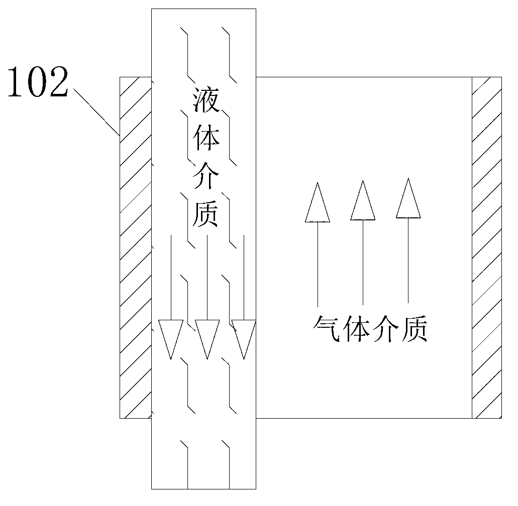
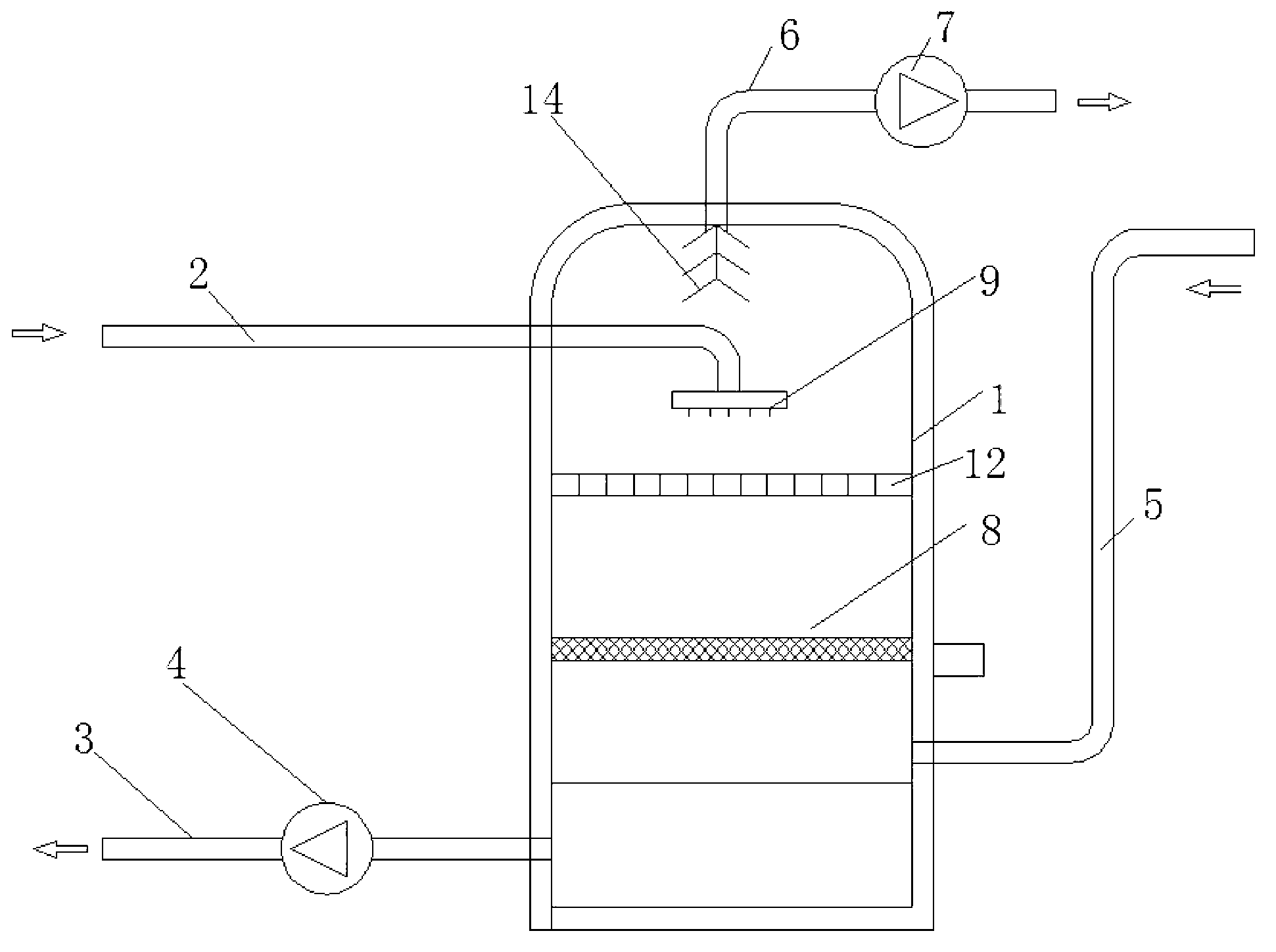
[0036] see Figure 3-Figure 8 , a supercooled water production device, comprising a container 1, a liquid distributor and a liquid collector located in the container, during specific implementation, the liquid distributor is a liquid inlet pipe 2, and the liquid collector is an outlet for discharging the liquid in the container A liquid pipe 3; a delivery pump 4 is added on the liquid outlet pipe 3; and an air inlet and an air outlet arranged on the container, the air inlet is connected with the air inlet pipe 5, the air outlet is connected with the air outlet pipe 6, and the air outlet pipe 6 A blower 7 for forming a negative pressure in the container is arranged on the top; a heatable supercooled liquid film forming part 8 is arranged inside the container 1, image 3 The supercooled liquid film forming part shown in is a plate type, which is...


PUM


Abstract

The invention belongs to the technical field of heat energy, and particularly relates to a super-cooled water preparation device for exchanging heat between gas and liquid. The super-cooled water preparation device comprises a container, a liquid distributor and a liquid trap which are positioned in the container, and an air inlet and an air outlet which are formed on the container, wherein a super-cooled liquid membrane forming part capable of heating is arranged in the container and is arranged between the liquid distributor and the liquid trap and between the air inlet and the air outlet; an included angle is formed between the super-cooled liquid membrane forming part and a liquid flow direction as well as between the super-cooled liquid membrane forming part and a gas flow direction; the surface of the super-cooled liquid membrane forming part is provided with a poor heat conducting layer; and when the super-cooled liquid membrane forming part heats, heat is slowly released to the surface of the poor heat conducting layer, and the liquid membrane temperature is controlled to be more than or equal to a liquid freezing point. Heat transferring mediums can be directly contacted, the heat exchange efficiency is high, the size is small, the manufacturing cost is low, and impurities can be removed from the gas heat transferring medium.

Description

technical field [0001] The invention belongs to the technical field of thermal energy, and in particular relates to a supercooled water production device for heat exchange between gas and liquid. Background technique [0002] The heat exchange mode between gas and liquid in the prior art adopts plate heat exchange or surface heat exchange; wherein, the plate heat exchange mode is, see figure 1 , a heat exchange plate 101 is arranged between the gas medium and the liquid medium, the gas medium passes through one side of the heat exchange plate and contacts the heat exchange plate, while the liquid medium passes through the other side of the heat exchange plate and contacts the heat exchange plate Plate contact, so that the heat of the liquid (gas) medium is first transferred to the heat exchange plate, and then the heat is transferred to the gas (liquid) medium through the heat exchange plate. There is no contact between the gas medium and the liquid medium, and the heat exch...

Claims


Application Information

Patent Timeline
Patent Type & Authority Applications(China)
IPC IPC(8): F28C1/00F28F25/00
Inventor 杨家华朱庭浩蒋丹丹
Owner 江苏河海新能源技术发展有限公司
Why Eureka
Try Eureka