
Automatic ball adding machine

A ball machine and automatic technology, applied in the direction of grain processing, etc., can solve the problems that affect the efficiency of the mill, the load of the motor is large, and the ball cannot be caught, etc., and achieve the effect of improving the efficiency of adding balls, low manufacturing cost, and easy maintenance

Active Publication Date: 2013-04-24
NANJING MEISHAN METALLURGY DEV
View PDF6 Cites 14 Cited by
  • Summary
  • Abstract
  • Description
  • Claims
  • Application Information

AI Technical Summary

Problems solved by technology

[0005] The claw-type chain lifting automatic ball feeding machine has the following disadvantages: the lifting track is easily deformed, resulting in ball jamming, and normal ball feeding cannot be realized; the ball loosening device at the bottom of the ball feeding chamber is overloaded because all the balls in the chamber are pressed on it. , causing the loose ball device not to work normally, and at the same time causing the motor to burn out, so that the steel ball in the ball chamber cannot reach the lifting position; the lifting claw is easily deformed and often cannot catch the ball
[0006] The barrel-type rotary lifting ball adding machine has the following disadvantages: when adding balls, most of the steel balls in the ball bin need to be driven to turn over, the motor load is heavy, and the motor is easy to break; When unloading balls from the loading bucket, the steel balls are not easy to come out of the loading bucket, especially the large-diameter steel balls with a diameter of ¢120mm are more likely to get stuck at the bottom of the loading bucket, resulting in poor unloading of the balls; waste of manpower
[0007] There are many defects in the above two automatic ball adding methods, which make the ball adding operation difficult, and in the actual production, it is easy to cause the steel ball filling rate in the mill to be unstable, which seriously affects the mill efficiency.

Method used


Image

  • Automatic ball adding machine
  • Automatic ball adding machine
  • Automatic ball adding machine

Examples


Embodiment Construction

[0031] The technical solutions provided by the present invention will be described in detail below in conjunction with specific examples. It should be understood that the following specific embodiments are only used to illustrate the present invention and are not intended to limit the scope of the present invention. It should be noted that the words "front", "rear", "left", "right", "upper" and "lower" used in the following description refer to the directions in the drawings, and the words "inner" and "outer ” refer to directions towards or away from the geometric center of a particular part, respectively.

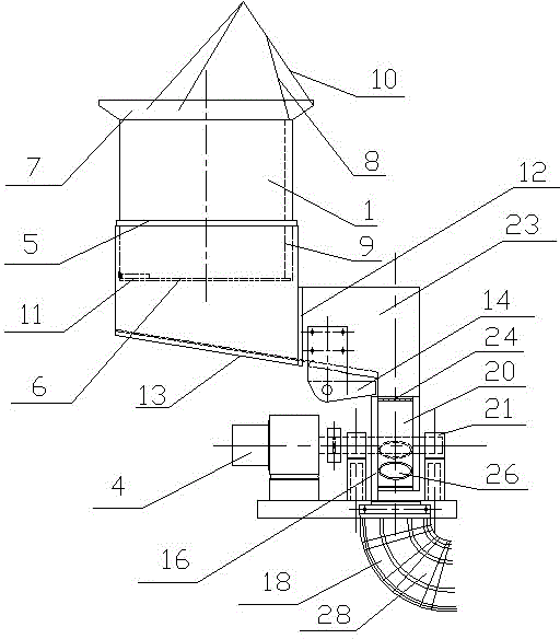
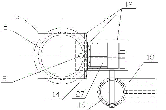
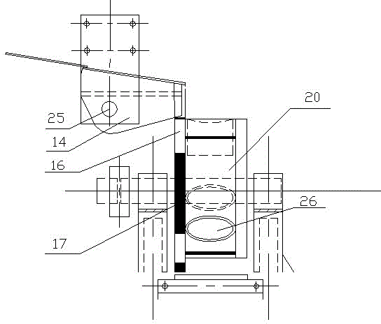
[0032] Such as figure 1 , figure 2 The electric ball adding machine for the ball mill shown includes a ball adding barrel 1, a ball adding bin 2, a buffer zone 23, a motor 4, a disc ball unloading device 15 and a lower ball tube 18, and the ball adding barrel 1 is cylindrical and is set In the ball adding bin 2, the top of the ball adding barrel 1 is higher than the upp...


PUM


Abstract

The invention designs a novel automatic ball adding machine which is suitable for adding balls into ball milling machines with various specifications, such as lattice-type ball mill, overflow type ball mill, semi-autogenous grinding ball mill, etc., and is accurate in ball adding amount, stable, and low in failure rate. The automatic ball adding machine provided by the invention comprises a ball adding barrel, a ball adding storehouse, a buffer area, a motor, a disc ball unloading machine and a ball uploading pipe. The automatic ball adding machine provided by the invention can effectively prevent occurrence of squeezing, stacking and blocking among the balls during a ball adding process, so that ball loading and unloading processes during a ball adding operation are quite smooth, and a ball adding number can be further calculated, thereby effectively improving ball adding efficiency. In addition, the ball adding machine is simple in structure, low in manufacture cost, convenient to maintain, and extremely low in failure rate, and is suitable for popularization and application in the ball adding process of the ball milling machines with various specifications.

Description

[0001] technical field [0002] The invention belongs to the field of electric machinery, and in particular relates to an electric ball adding machine suitable for adding balls to ball mills of various models and specifications. Background technique [0003] Ball mill is the key equipment for crushing materials after being crushed. It is widely used in cement, silicate products, new building materials, refractory materials, chemical fertilizers, black and non-ferrous metal beneficiation and glass ceramics and other production industries. Other grindable materials are subjected to dry or wet grinding. The ball mill is generally a horizontal cylinder with a built-in grinding body. The grinding body is generally a steel ball. Before grinding, steel balls with different diameters and a certain proportion are loaded into the cylinder according to the processing requirements. [0004] The existing ball mill adding methods include manual adding ball and automatic ball adding, ...

Claims


Application Information

Patent Timeline
IPC IPC(8): B02C17/18
Inventor 马少华
Owner NANJING MEISHAN METALLURGY DEV
Learn More