
Full-range pulse-width modulation charging technology for photovoltaic power generation

A technology of pulse width modulation and photovoltaic power generation, which is applied to battery circuit devices, current collectors, electric vehicles, etc., can solve problems such as rising system costs, battery outgassing, and empty batteries, so as to reduce maintenance costs and overall costs , the effect of reducing the degree of vulcanization

Inactive Publication Date: 2013-04-17
YUNNAN JUNHE TECH
View PDF4 Cites 2 Cited by
  • Summary
  • Abstract
  • Description
  • Claims
  • Application Information

AI Technical Summary

Problems solved by technology

Using DC charging will cause the battery to be full and the battery will gas out, which will affect the service life of the battery
Using three-period charging, although the battery can be fully charged, but because the second and third periods of charging use pulse charging, when the switch circuit [2] is closed, the energy generated by the solar module because the circuit has no intermediate energy storage device is is wasted, resulting in a corresponding increase in system cost when configuring the system
At the same time, regardless of the three-period charging or DC charging, the voltage of the solar cell module cannot be controlled, so that the maximum power point of the solar cell module cannot be tracked at all. Therefore, the known charging method cannot be used in system configuration or later maintenance. achieve better results

Method used


Image

  • Full-range pulse-width modulation charging technology for photovoltaic power generation
  • Full-range pulse-width modulation charging technology for photovoltaic power generation
  • Full-range pulse-width modulation charging technology for photovoltaic power generation

Examples


Embodiment 1

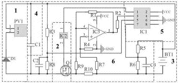
[0016] Embodiment 1: as image 3 The one shown uses an energy storage capacitor as an intermediate energy storage device. The connection mode between the various electronic components is that the positive pole of the solar module PV1 is connected to the positive pole of the capacitor C1, the negative pole of the solar module PV1 is connected to the positive pole of the diode D1, and the diode The negative pole of D1 is connected to the negative poles of capacitors C1 and C2, the resistor R8 is connected in parallel with capacitor C2, the other end of resistor R8 is connected to one end of resistor R3, and the other end of R3 is connected to the positive pole of solar module PV1. The source of the field effect transistor Q1 is connected to the cathode of the diode D1, the gate of the field effect transistor Q1 is connected to the second pin of the driver chip IC2, the drain resistor R9 of the field effect transistor Q1 and one end of the resistor R10, the resistor R10 The other...

Embodiment 2

[0017] Embodiment 2: as Figure 4 The one shown uses energy storage capacitors as intermediate energy storage devices. In some ordinary low-power controllers, in order to reduce costs and increase product price competitiveness, the design of some data acquisition and control circuits can be appropriately simplified. The connection method is as follows: the positive pole of the solar photovoltaic module PV1 is connected to the positive pole of the energy storage capacitor C1, the negative pole of the solar photovoltaic module PV1 is connected to the positive pole of the diode D1, the negative pole of the diode D1 is connected to the negative pole of the energy storage capacitor C1, the capacitor C2 and the resistor R3 One end of the parallel connection is connected to the negative pole of the energy storage capacitor, the other end is connected to the first pin of the central processing unit IC2, one end of the resistor R1 is connected to the positive pole of the solar photovolt...


PUM


Abstract

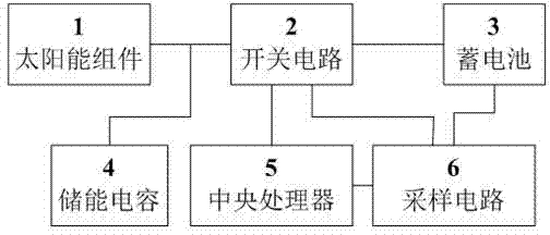
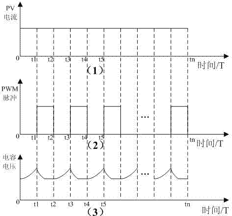
The invention relates to a full-range pulse-width modulation charging technology for photovoltaic power generation. The full-range pulse-width modulation charging technology comprises a solar component, a switch circuit, a storage battery, an energy-storage capacitor, a central processor and a sampling circuit. Due to the arrangement of the energy-storage capacitor and the adoption of a PWM (pulse-width modulation) control method, the capacitor voltage can be controlled, so that the maximal power point of the solar component can be found out and the tracking of the maximal powder point of a photovoltaic module can be achieved. The charging method of keeping the pulse-width modulation mode all the time in a charging process is achieved, so as to improve the utilization rate of the component and reduce the vulcanization degree of the storage battery, so that the purposes of prolonging the service life of the storage battery and reducing the configuration cost of the component are achieved.

Description

technical field [0001] The invention relates to a full-range pulse width modulation charging technology for photovoltaic power generation, and belongs to the technical field of photovoltaic application control. Background technique [0002] It is predicted that solar photovoltaic power generation will occupy an important seat in the world's energy consumption in the 21st century, not only to replace some conventional energy sources, but also to become the main body of the world's energy supply. It is estimated that by 2030, renewable energy will account for 30% of the total energy structure, and solar photovoltaic power generation will account for 10% of the world's total power supply; by 2040, renewable energy will account for total energy consumption By the end of the 21st century, renewable energy will account for 80% of the energy structure, and solar power will account for 60%. These figures are enough to show the development prospects of the solar photovoltaic industr...

Claims


Application Information

Patent Timeline
Patent Type & Authority Applications(China)
IPC IPC(8): H02J7/00
Inventor 杨建国夏义军周幸
Owner YUNNAN JUNHE TECH
Learn More