Convenient-to-place multi-side charging wireless positioning terminal

A wireless positioning and positioning terminal technology, which is applied to circuits, current collectors, electric vehicles, etc., can solve the problems that users cannot distinguish between the front and back, the effect of charging, and poor contact. It achieves simple structure, low manufacturing cost, Reduce the effect of direct contact

Inactive Publication Date: 2013-04-17
CHENGDU RUIYI INFORMATION TECH
View PDF3 Cites 3 Cited by
  • Summary
  • Abstract
  • Description
  • Claims
  • Application Information

AI Technical Summary

Problems solved by technology

The positioning terminal itself needs to consume power during use, so it needs to be charged. Generally, the charging design of the positioning terminal is to use an external IO socket for charging. After a period of use, the socket will appear loose, resulting in loose contact. The effect of charging is affected. At the same time, because the traditional positioning terminal adopts two sockets, that is, one positive pole and one negative pole, it can only be used for charging in one direction. Since the shape of the positioning terminal adopts a symmetrical design, users often Can't tell the front and back, causing a lot of trouble during the charging process

Method used


Image

  • Convenient-to-place multi-side charging wireless positioning terminal
  • Convenient-to-place multi-side charging wireless positioning terminal

Examples


Embodiment 1

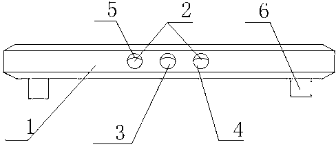
[0017] Such as figure 1 As shown, the multi-surface charging wireless positioning terminal that is easy to place includes a positioning terminal body 1, and a plurality of charging sockets 4 are arranged on the positioning terminal body 1, and the charging sockets 4 are all communicated with the interior of the positioning terminal body 1, and the charging A contact shrapnel 5 is arranged inside the socket 4 . When the plug is inserted into the charging socket 4, the contact shrapnel 5 retracts when the contact shrapnel 5 is touched, and pops up automatically after the charging is completed, preventing dust from entering the positioning terminal body 1, and can accurately guide the positioning of the plug.

[0018] The number of charging sockets 4 is three. The three charging sockets 4 form a crossing charging socket 4, which can satisfy the front and back charging of the positioning terminal body 1. The electrodes of the charging sockets 4 on both sides of the charging sock...

Embodiment 2

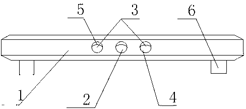
[0021] Such as figure 2 As shown, the charging socket 4 in the middle is the positive pole 2, and the charging sockets 4 on both sides are the negative pole 3, which is convenient for users to use quickly, and will not cause failure to charge or burn out the positioning terminal due to wrong insertion of the positive pole 2 and negative pole 3 Ontology 1.

Embodiment 3

[0023] The structure of this embodiment is basically the same as that of Embodiment 1, the only difference being that the bottom ends of the support columns 6 are on the same horizontal plane. The support column 6 is used to support the positioning terminal body 1. During use, it ensures that the bottom end of the positioning terminal body 1 will not contact the contact surface, keep it clean and level, and improve the service life of internal components. The bottom end of the positioning terminal body 1 is provided with several support columns 6 . When charging, insert the plug into the charging socket 4 to quickly charge the positioning terminal body 1 . The positioning terminal body 1 is supported by the support column 6 to maintain the stability of the positioning terminal body 1 and avoid contact static electricity.


PUM


Abstract

The invention discloses a convenient-to-place multi-side charging wireless positioning terminal, which comprises a positioning terminal body, wherein a plurality of charging jacks are arranged in the positioning terminal body and are respectively communicated with the inside of the positioning terminal body, and a plurality of support posts are arranged at the bottom end of the positioning terminal body. The wireless positioning terminal has the advantages that the structure is simple, the manufacture cost is low, the operation principle is convenient, three jacks can be utilized for fast charging the positioning terminal, meanwhile, the jacks can be precisely aligned with an electrode through contact type elastic sheets, the direct contact with the ground is reduced, and the corrosion on the equipment caused by water vapor is avoided.

Description

technical field [0001] The invention relates to a wireless positioning terminal, in particular to an easy-to-place wireless positioning terminal with multi-surface charging. Background technique [0002] After the energy of the battery is consumed by discharge, it can be recovered by charging and can be discharged again to form a charge-discharge cycle. Generally, DC current (also useful for asymmetric AC current or pulse current) is used for charging. In different situations, different charging methods such as constant current charging, constant voltage charging, floating charging, trickle charging, rapid charging or a combination of these methods are used. There are many chargers, such as lead-acid battery chargers, testing and monitoring of valve-regulated sealed lead-acid batteries, nickel-cadmium battery chargers, nickel-metal hydride battery chargers, lithium-ion battery chargers, lithium-ion battery chargers for portable electronic devices, Lithium-ion battery prote...

Claims


Application Information

Patent Timeline
Patent Type & Authority Applications(China)
IPC IPC(8): H02J7/00H01R13/52H01R13/631
Inventor 任佳
Owner CHENGDU RUIYI INFORMATION TECH
Why Eureka
Try Eureka