
An antistatic structure of an electronic detonator

An electronic detonator and anti-static technology, used in weapon accessories, fuzes, offensive equipment, etc., can solve the problems of the existence of electronic detonator structure, no electrical connection, inability to discharge, etc., to ensure anti-static, prevent false explosion, and resist tension strong effect

Active Publication Date: 2015-09-16
BEIJING QAML OF SCI & TECH CO LTD
View PDF8 Cites 0 Cited by
  • Summary
  • Abstract
  • Description
  • Claims
  • Application Information

AI Technical Summary

Problems solved by technology

There is a big problem in these products: there is no electrical connection between the foot wire and the metal detonator shell. When there is static electricity between the foot wire and the shell, it cannot be discharged, which is likely to cause safety hazards
[0004] Although the patent application document 98232749.8 proposes the method of using conductive rubber or conductive engineering plastics to make the plug, this method can only reduce the static electricity generated between the foot line and the detonator. When the personnel who produce or use the detonator contact the metal shell of the detonator with static electricity, It will be impossible to avoid the occurrence of electrostatic discharge sparks in the tube
[0005] It can be seen that there are still potential safety hazards in the structure of the existing electronic detonators, which need to be solved by those skilled in the art.

Method used


Image

  • An antistatic structure of an electronic detonator
  • An antistatic structure of an electronic detonator
  • An antistatic structure of an electronic detonator

Examples


Embodiment Construction

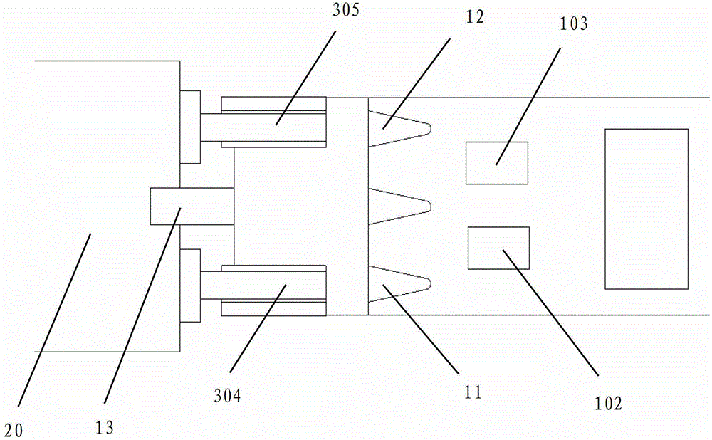
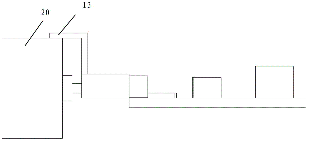
[0025] see figure 1 , figure 2 , image 3 As shown, the antistatic structure of the electronic detonator provided by the present invention is mainly applicable to parallel electronic detonators. Connectors 12 and discharge metal connectors 13 (both sheets in this embodiment), the first and second metal connectors 11, 12 are respectively connected between the two legs 304, 305 and the control circuit The control circuit 303 of the board 300 (as Image 6 As shown), one end of the discharge metal connector 13 is fixed on the control circuit 303 board 300, and the other end is close to the cylindrical surface of the insulating sealing plug 20 closest to the control circuit board and the metal shell 302 of the electronic detonator (such as Image 6 Shown) the inner wall of the conductive connection.

[0026] Such as Figure 4 , Figure 5 As shown, the three metal connectors 11, 12, 13 are insulated from each other, and are integrated by injection molding of high-resistance m...


PUM


Abstract

The invention provides an anti-static structure of an electronic detonator, wherein two leg wires of the electronic detonator are electrically connected with a control circuit of a control circuit board. The anti-static structure of the electronic detonator is characterized by further comprising a discharge metal connecting piece; one end of the discharge metal connecting piece is electrically connected with a metal casing of the electronic detonator; two anti-static electronic devices are connected between the other end of the discharge metal connecting piece and one leg wire, as well as between the other end of the discharge metal connecting piece and the other leg wire respectively; and the anti-static electronic devices are transient suppression diodes, discharge tubes or voltage dependent resistors. By additionally arranging the anti-static structure on the electronic detonator, electricity can be preferentially discharged through the anti-static devices when the electronic detonator carries out electrostatic discharge, so that an error explosion can be prevented in the production and use processes; and moreover, one leg wire of the electronic detonator is connected with a first metal connecting piece and a second metal connecting piece in a manner of metal compression joint, the connecting operation is simple, tensile resistance is strong, and the electronic detonator can be prevented from being damaged by an external force in the production and use processes.

Description

technical field [0001] The invention relates to a detonator structure, in particular to an antistatic structure of a parallel electronic detonator. Background technique [0002] The electronic detonator sequentially includes a foot wire, a control circuit board with a delay chip, an ignition powder head and a priming charge. When in use, connect the busbar for outputting the detonation signal to the foot wire, then output the detonation serial signal, the delay chip performs a predetermined time delay, and then the control circuit board passes the detonation signal through the bridge wire Pass it to the ignition powder head to realize detonation control. [0003] The legs of the existing electronic detonator are formed by injection molding with the sealing plug at the end of the detonator, and are mostly connected with the reserved pads of the control circuit board by soldering. The connection form of the bridge wire between the control circuit board and the ignition charg...

Claims


Application Information

Patent Timeline
Patent Type & Authority Patents(China)
IPC IPC(8): F42C19/12
Inventor 银庆宇
Owner BEIJING QAML OF SCI & TECH CO LTD
Learn More