Light emitting diode (LED) drive circuit controlled by parallel connection high voltage metal oxide semiconductor (MOS) tube

A technology of LED drive and MOS tube, which is applied in the direction of lamp circuit layout, electric light source, lighting device, etc., can solve the problems of service life impact, unsatisfactory power factor, low cost, etc., and achieve reduction in volume and cost, and circuit conversion efficiency High, the effect of increasing the service life

Active Publication Date: 2013-04-03
深圳德信微电子有限公司
View PDF3 Cites 12 Cited by
  • Summary
  • Abstract
  • Description
  • Claims
  • Application Information

AI Technical Summary

Problems solved by technology

The advantages of this kind of circuit are high efficiency, high safety standards, and more accurate control of the output current; but because it requires more peripheral devices and contains control ICs, the circuit cost is high, the volume is large, and the power factor is also due to A large input capacitance is not ideal; to achieve DC drive, it must also contain a large electrolytic capacitor, which will affect the service life
[0012] To sum up, the current traditional LED drive circuit cannot take into account the comprehensive advantages of low cost, high efficiency, high power factor, small size, etc., and there is a lot of room for improvement

Method used


Image

  • Light emitting diode (LED) drive circuit controlled by parallel connection high voltage metal oxide semiconductor (MOS) tube
  • Light emitting diode (LED) drive circuit controlled by parallel connection high voltage metal oxide semiconductor (MOS) tube
  • Light emitting diode (LED) drive circuit controlled by parallel connection high voltage metal oxide semiconductor (MOS) tube

Examples


Embodiment Construction

[0030] The present invention will be further described below in conjunction with accompanying drawings and embodiments thereof.

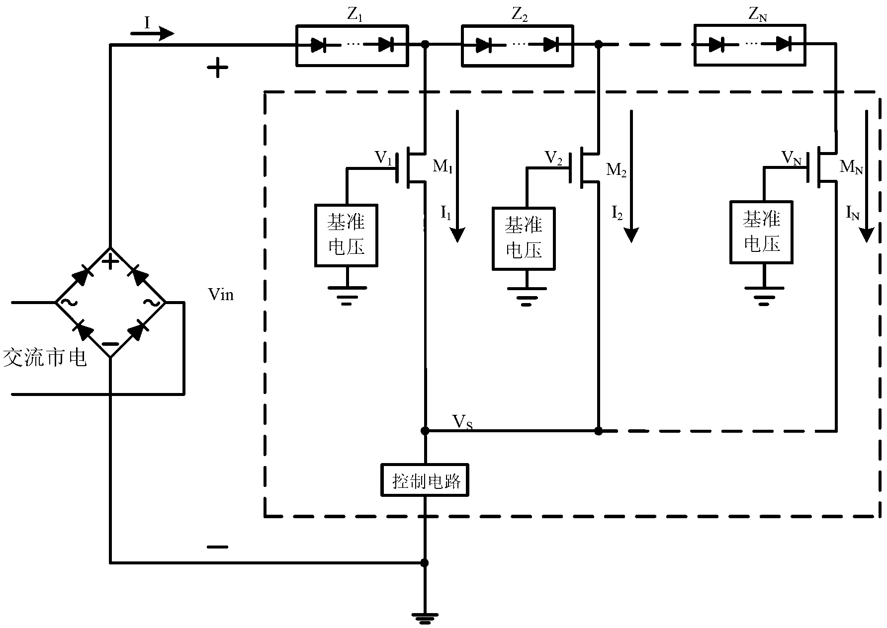
[0031] refer to image 3 , LED driver circuit of the present invention comprises: rectifier bridge, control circuit N series load Z 1 ~ Z N , N high-voltage MOS tubes M 1 ~ M N and N voltage reference circuits, N≥1; where:

[0032] A rectifier bridge for full-wave rectification of AC signals;

[0033] N series load Z 1 ~ Z N , a single group connected in series to form a variable load network, and connected across the rectifier bridge and the Nth high-voltage MOS tube M N Each string of loads is composed of L light-emitting diodes LEDs connected in series, L×N<100;

[0034] N high voltage MOS tubes M 1 ~ M N , used to control the load size of the access circuit; the source of each high-voltage MOS tube is connected to the control circuit; the gate of each high-voltage MOS tube is connected to N voltage references; the first high-voltage MO...


PUM


Abstract

The invention discloses a light emitting diode (LED) drive circuit controlled by a parallel connection high voltage metal oxide semiconductor (MOS) tube and mainly solves the problem that existing drive circuits can not integrate effects of low costs and high efficiency and power factors. The LED drive circuit comprises a rectifier bridge, a control circuit, N strings of loads, N high voltage MOS tubes and N voltage reference circuits, the rectifier bridge is used for performing full-wave rectification for an alternating current signal, the N strings of loads are in a series connection in a single group mode and are in a bridge joint between the rectifier bridge and a drain electrode of the Nth high voltage MOS tube, common ends of two adjacent strings of loads are connected to drain electrodes of corresponding high voltage MOS tubes respectively, grid electrodes of the N high voltage MOS tubes are connected with the N voltage reference circuits respectively, source electrodes of the N high voltage MOS tubes are connected and connected to the control circuit, the control circuit detects current of the loads to adjust the voltage of the source electrodes of the high voltage MOS tubes so as to control the working states of the high voltage MOS tubes, and thereby the loads of an access circuit can be adjusted. The LED drive circuit controlled by parallel connection high voltage MOS tube has the advantages that peripheral devices are few, the service life is long, the efficiency and power factor are high, and the LED drive circuit can be directly integrated on a lamp panel carried with LED strings.

Description

technical field [0001] The invention belongs to the technical field of electronic circuits, relates to an LED driving circuit and can be used for analog integrated circuits. Background technique [0002] In lighting applications, light-emitting diodes (LEDs) are considered to be one of the most potential light sources at present because of their high luminous efficiency, long life, high brightness, energy saving, environmental protection and durability. In order to give full play to its advantages and be fully compatible with the previous generation of lighting products such as incandescent lamps and energy-saving lamps, it is necessary to equip an LED drive circuit with small size, long life, low cost, and directly powered by AC mains to maximize Give full play to the advantages of LED itself. At present, there are many kinds of LED drive circuits powered by AC mains, which can be mainly divided into two categories. [0003] refer to figure 1 , the first type is the driv...

Claims


Application Information

Patent Timeline
Patent Type & Authority Applications(China)
IPC IPC(8): H05B37/02
Inventor 来新泉韩杰邵丽丽何惠森
Owner 深圳德信微电子有限公司
Why Eureka
Try Eureka