Modular design method of large-capacity battery energy storage system
A technology of battery energy storage system and modular design, which is applied in the direction of electric energy storage system, flexible AC transmission system, battery circuit device, etc.
- Summary
- Abstract
- Description
- Claims
- Application Information
AI Technical Summary
Problems solved by technology
Method used
Image
Examples
Embodiment approach 1
[0019] Implementation Option 1: Application Mode of Peak Shaving and Valley Filling
[0020] In the application mode of peak shaving and valley filling, the typical capacity of the energy storage system is several hundred kW-tens of MW, and the time is 2-4h. This implementation plan takes the 1MW / 4MWh energy storage system as an example to carry out the scheme design.
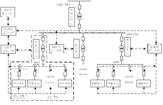
[0021] The 1MW / 4MWh energy storage system is composed of one 1MW / 4MWh energy storage circuit, and each energy storage circuit is composed of four 250kW / 1MWh energy storage branches. The grid circuit breaker is connected to the 35kV busbar, such as Figure 4 shown.
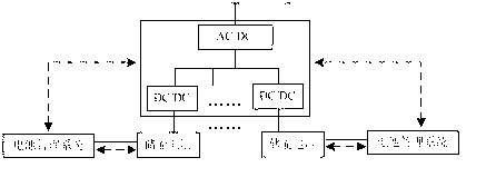
[0022] The 250kW / 1MWh energy storage unit adopts a 250kW two-stage energy storage converter and five parallel 200kWh battery strings. The topology is as follows: Figure 5 shown. Each 200kWh battery string is composed of 180 3.2V / 360Ah unit batteries in series, with a working voltage range of 450-657V and a rated voltage of 576V. The compositio...
specific Embodiment approach 2
[0023] Specific implementation plan 2: new energy access application mode
[0024] In the new energy access mode, the energy storage system is used in conjunction with large-scale wind farms or photovoltaic power generation to smooth the output of wind power and photovoltaic power generation and improve the grid's ability to accept new energy. The typical capacity of the energy storage system is several MW-hundreds of MW, and the time is 2-4h. This implementation plan takes the 10MW / 20MWh energy storage system as an example for scheme design.
[0025] The 10MW / 20MWh energy storage system consists of five 2MW / 4MWh energy storage circuits, and each energy storage circuit consists of four 500kW / 1MWh energy storage branches. The grid circuit breaker is connected to the 35kV busbar, such as Figure 6 shown.
[0026] The 500kW / 1MWh energy storage unit adopts a 500kW two-stage energy storage converter and ten parallel 100kWh battery strings. The topology is as follows: Figure 7 ...
specific Embodiment approach 3
[0027] Specific implementation plan 3: application mode of peak regulation and frequency regulation
[0028] In the peak-shaving and frequency-regulating power station application mode, the energy storage system compensates the grid for active or reactive power, which can improve the power quality of the grid. The typical capacity of the energy storage system is tens of MW to hundreds of MW, and the time is 15 minutes to 1 hour. This implementation plan takes the 20MW / 5MWh energy storage system as an example to design.
[0029] The 20MW / 5MWh iron-lithium battery energy storage system consists of ten 2MW / 0.5MWh energy storage circuits. Each energy storage circuit is connected to the 400V bus, and connected to the 35kV bus through a 0.4 / 35kV step-up transformer unit, such as Figure 8 shown.
[0030] The 20MW / 5MWh iron-lithium battery energy storage system consists of 10 2MW / 0.5MWh energy storage circuits, and each energy storage circuit consists of 4 energy storage branches....
PUM
 Abstract
Description
Claims
Application Information
 - R&D
- Intellectual Property
- Life Sciences
- Materials
- Tech Scout
- Unparalleled Data Quality
- Higher Quality Content
- 60% Fewer Hallucinations
Browse by: Latest US Patents, China's latest patents, Technical Efficacy Thesaurus, Application Domain, Technology Topic, Popular Technical Reports.
© 2025 PatSnap. All rights reserved.Legal|Privacy policy|Modern Slavery Act Transparency Statement|Sitemap|About US| Contact US: help@patsnap.com


