Antenna of electronic tag

An electronic tag and antenna technology, applied in the field of radio frequency communication, can solve the problems that the antenna cannot be matched to the resonant frequency, the antenna inductance is reduced, etc., and achieve the effect of simple structure, small size and good practicability

Inactive Publication Date: 2013-04-03
上海祯显电子科技有限公司
View PDF0 Cites 3 Cited by
  • Summary
  • Abstract
  • Description
  • Claims
  • Application Information

AI Technical Summary

Problems solved by technology

From the perspective of reducing the size of the RF antenna, after reducing the size of the RF antenna, the inductance of the antenna will decrease, and the length of the antenna cannot match the requirements of the resonance frequency. In the case of matching the input capacitance of the same chip, it is necessary to add an external matching capacitor. In order to reach the resonant frequency of 860-960MHz

Method used


Image

  • Antenna of electronic tag
  • Antenna of electronic tag
  • Antenna of electronic tag

Examples


Embodiment Construction

[0029] In order to make the technical means, creative features, goals and effects achieved by the present invention easy to understand, the present invention will be further described below in conjunction with specific illustrations.

[0030] The technology of the electronic tag antenna of the present invention will effectively reduce the external dimension of the electronic tag antenna, realize the miniaturization of the volume of the UHF electronic tag, and obtain a miniaturized, high-reliability UHF electronic tag product, and then provide a solution technology The implementation plan is as follows:

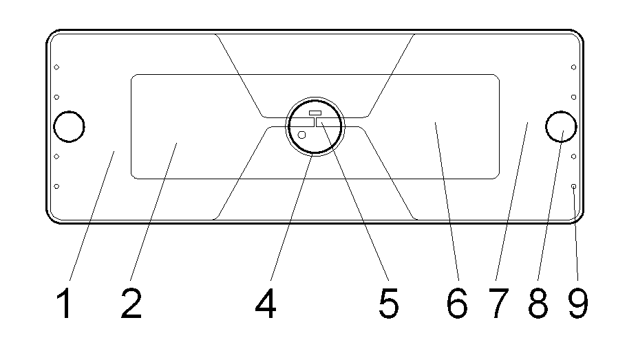
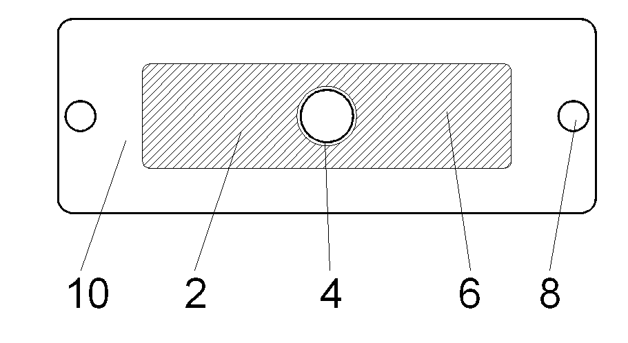
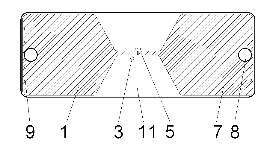
[0031] see figure 1 and Image 6 , the electronic tag antenna of the present invention is mainly composed of antenna insulating dielectric layer 11, signal radiation unit layers 1 and 7, via hole 9, ground plane metal layer 12, capacitor metal layers 2 and 6, and capacitor insulating dielectric layer 10. The antenna is insulated The dielectric layer 11 is a relatively thick...


PUM


Abstract

The invention discloses an antenna of an electronic tag. The antenna comprises an antenna insulating dielectric layer, signal radiation unit layers, via holes, a ground plane metal layer, capacitance metal layers and a capacitance insulating dielectric layer; the antenna insulating dielectric layer is of a thick insulating plate structure, the signal radiation unit layers and the ground plane metal layer are respectively attached to the front surface and the back surface of the antenna insulating dielectric layer and form two conductive layers, the via holes are arranged at ends, which are far away from a chip mounting position, of the signal radiation unit layers, and the signal radiation unit layers and the ground plane metal layer are conducted with one another to form a circuit via the via holes; and the capacitance insulating dielectric layer is of a thin insulating plate structure, the capacitance metal layers are arranged on one surface of the capacitance insulating dielectric layer, and the other surface of the capacitance insulating dielectric layer is in press fit with the signal radiation unit layers. The antenna of the electronic tag can be minimized, and can be applied to anti-metal electronic tags.

Description

technical field [0001] The invention relates to the field of radio frequency communication and the field of smart labels, in particular to an antenna for an electronic label. Background technique [0002] In recent years, due to the continuous development of radio frequency electronic technology, especially the wide application of radio frequency electronic tags, people's way of life is gradually changing. Common radio frequency electronic tags are divided into two categories: active and passive in terms of power supply; in terms of carrier frequency, there are 125KHz (130KHz) low-frequency bands, 13.56MHz high-frequency bands, 433MHz, 915MHz ultra-high frequency bands , 2.4GHz, 5.8GHz microwave frequency band; the application of electronic tags is ubiquitous, so there are various shapes and products suitable for different application requirements, making people's life more convenient and efficient. [0003] In order to make radio frequency electronic tags more widely used ...

Claims


Application Information

Patent Timeline
Patent Type & Authority Applications(China)
IPC IPC(8): H01Q1/38H01Q1/22
Inventor 陆红梅
Owner 上海祯显电子科技有限公司
Why Eureka
Try Eureka