
Measuring method and device for transmittance of optical element

A technology of optical components and measuring devices, applied in the field of laser measurement, to achieve the effect of eliminating repeatability, accurate and convenient measurement

Active Publication Date: 2013-04-03
RAINBOW SOURCE LASER RSLASER
View PDF4 Cites 34 Cited by
  • Summary
  • Abstract
  • Description
  • Claims
  • Application Information

AI Technical Summary

Problems solved by technology

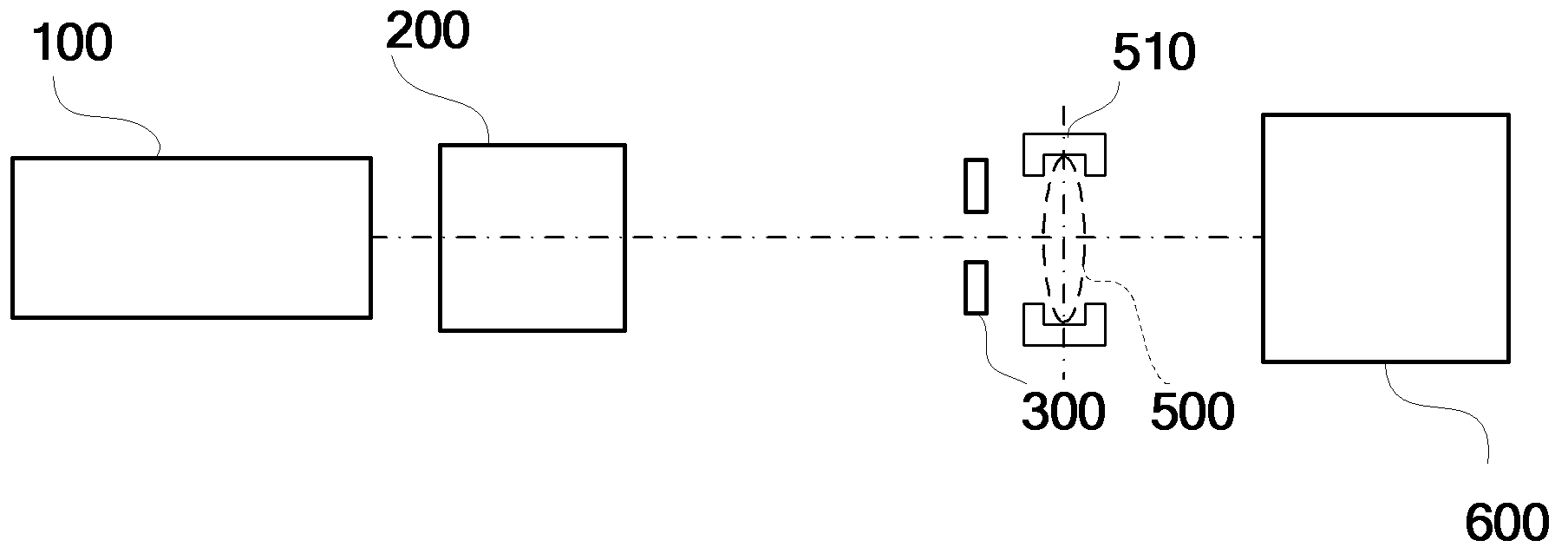
[0007] This patent intends to solve the problem of obtaining a more accurate transmittance value when the energy of the light source itself is unstable. Designing a suitable optical path and optimizing the measurement conditions can realize the transmittance of optical elements under the condition of large energy and high repetition frequency. high-precision measurement

Method used


Image

  • Measuring method and device for transmittance of optical element
  • Measuring method and device for transmittance of optical element
  • Measuring method and device for transmittance of optical element

Examples


no. 1 example

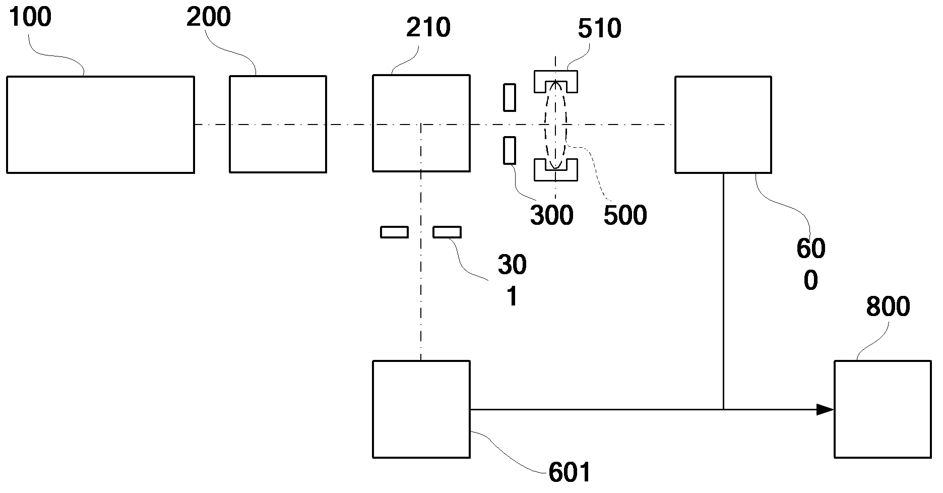
[0032] figure 2 It is a structural schematic diagram of the first embodiment of the optical element transmittance measurement device for high-energy, high-repetition-frequency ultraviolet pulse laser proposed by the present invention. Such as figure 2 As shown, the device is a dual optical path dual probe (photodetector) device, including a laser light source 100, an optical attenuator 200, a beam splitter 210, a first small hole plate 300, a second small hole plate 301, a Component holding device 510 , first photodetector 600 , second photodetector 601 and computer 800 . The optical element measured by the device of this embodiment is the lens 500 .

[0033] The laser light source 100 is an ultraviolet pulsed laser light source for generating ultraviolet pulsed laser light. The optical attenuator 200 is configured to receive the ultraviolet pulsed laser emitted by the laser light source 100 , and control the energy of the ultraviolet pulsed laser within the threshold ran...

no. 2 example

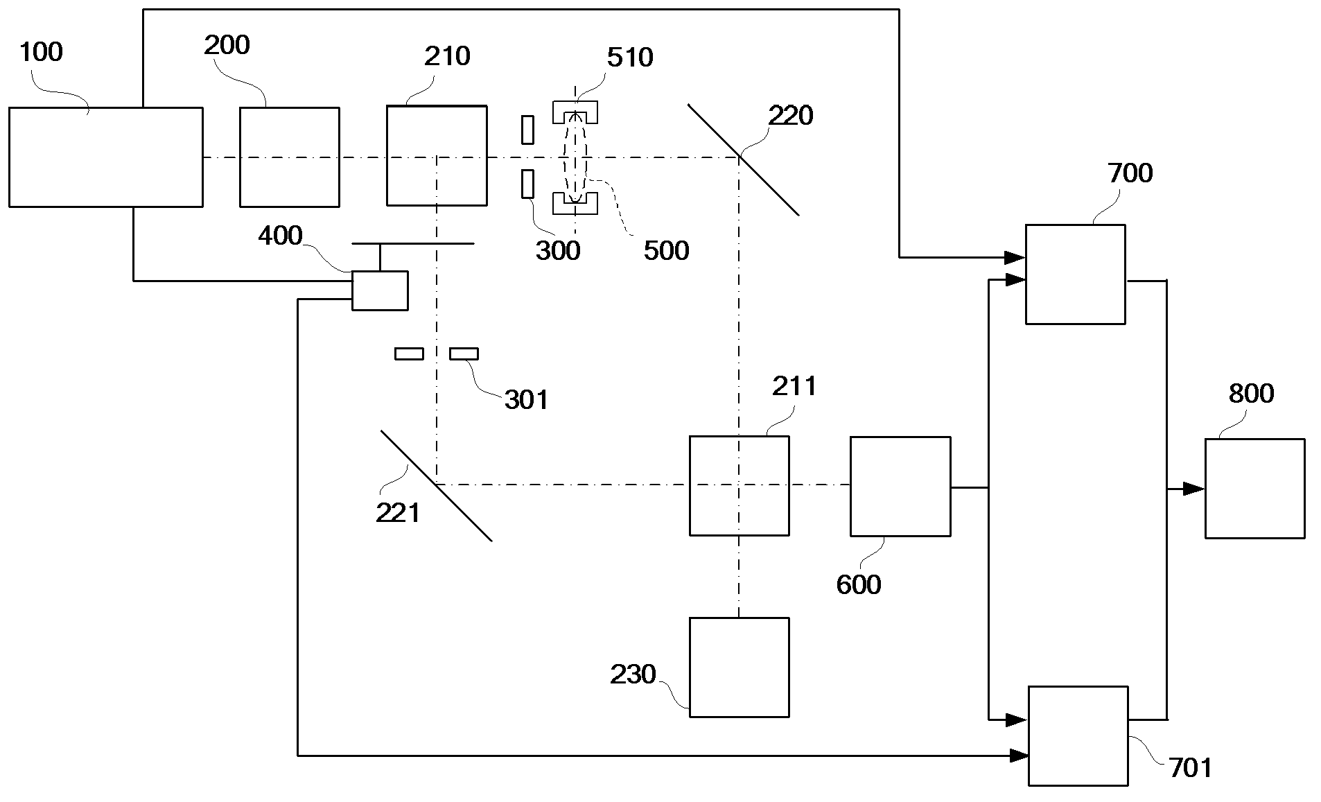
[0043] image 3 It is a structural schematic diagram of the second embodiment of the optical element transmittance measurement device for high-energy, high-repetition-frequency ultraviolet pulse laser proposed by the present invention. Such as image 3 As shown, the device is a dual optical path single probe (photodetector) device, including a laser light source 100, an optical attenuator 200, a beam splitter 210, a first small hole plate 300, a second small hole plate 301, an optical chopper Waveformer 400, first reflector 220, second reflector 221, beam splitter 211, beam collector 230, device under test clamping device 510, photodetector 600, first lock-in amplifier 700 and second lock-in amplifier amplifier 701 and computer 800. The optical element measured by the device of the second embodiment is also the lens 500 .

[0044] The laser light source 100 is an ultraviolet pulsed laser light source, which is used to generate 1 UV pulsed laser. At the same time, the lase...


PUM


Abstract

The invention discloses a measuring method and device for transmittance of an optical element. The method comprises the steps of splitting a laser beam with a specific wavelength to obtain two beams of laser, enabling the two beams of laser to pass through a reference light path and a measuring light path respectively, not placing the optical element on the measuring light path, and obtaining energy E1 of the laser beam passing through the reference light path and energy E2 of the laser passing through the measuring light path by measurement; placing the optical element on the measuring light path, and obtaining energy E1' of the laser beam passing through the reference light path and energy E3 of the laser passing through the measuring light path by measurement; and calculating the transmittance T of the optical element according to an equation T=(E1*E3) / (E1'*E2). According to the measuring method and device, Dual light path aplanatism measurement is adopted, the aim of real-time on-line measurement is achieved, influence of light source energy shake on repeatability of measuring results and measurement of the transmittance of a light-transmission lens can be effectively eliminated, and the transmittance of the optical element used for any ultraviolet pulse laser can be measured accurately and conveniently.

Description

technical field [0001] The invention belongs to the technical field of laser measurement, and in particular relates to a method and a device for measuring the transmittance of an optical element, in particular to a method and a device for measuring the transmittance of an optical lens for a high-energy, high-repetition-frequency ultraviolet pulse laser. Background technique [0002] The transmittance of an optical element refers to the ratio of the radiant luminous flux emitted from the optical element to the radiant luminous flux projected on the optical element, which is an important indicator of the energy transmission of the optical element. Since the transmittance of an optical element directly reflects the loss of its radiation luminous flux and the quality of the image, it is very important to measure the transmittance of an optical element. [0003] At present, the commonly used method for measuring the laser transmittance of optical components is the single-channel ...

Claims


Application Information

Patent Timeline
Patent Type & Authority Applications(China)
IPC IPC(8): G01M11/02
Inventor 周翊宋兴亮范元媛沙鹏飞赵江山李慧鲍洋张立佳崔惠绒王宇
Owner RAINBOW SOURCE LASER RSLASER
Learn More