Electronic expansion valve

A technology of electronic expansion valve and valve body, which is applied in the direction of valve details, valve device, valve operation/release device, etc. It can solve the problems that grounding cannot be realized, grounding cannot be guaranteed, and the contact of magnetic conductor cannot be absolutely guaranteed, so as to avoid damage Effect

Active Publication Date: 2014-12-03
ZHEJIANG SANHUA INTELLIGENT CONTROLS CO LTD
View PDF4 Cites 2 Cited by
  • Summary
  • Abstract
  • Description
  • Claims
  • Application Information

AI Technical Summary

Problems solved by technology

[0005] In the above structure, when the electrical signal is abnormal inside the plastic casing 2'3, such as the voltage rises or becomes ultra-high voltage, in order to prevent the coil 2' from being damaged, the stator casing inside the coil 2' needs to be 2'2 or the electromagnetic pole plate 2'1 is grounded, thereby leading out high voltage electricity; in the above structure, parts such as the electromagnetic pole plate 2'1 and the stator shell 2'2 are injected into the interior of the plastic shell 2'3 through the injection molding process , wherein the stator shell 2'2 and the electromagnetic pole plate 2'1 are in contact with each other, but there is no contact between the buckle 4' and the stator shell 2'2 due to the isolation of the plastic shell 2'3, thus Cannot be grounded
In the above structure, such as figure 2 As shown, the only parts inside the coil 2' that may be in contact with the valve body 1' are the claw poles in the inner hole of the magnetizer. However, since the fit between the coil 2' and the valve body 1' is a clearance fit, it cannot be absolutely Ensure that the claw poles in the inner hole of the magnetic conductor are in contact with the valve body 1', that is, when the electrical signal inside the coil 2' becomes high voltage or ultra-high voltage, the coil 2' may still be damaged because the grounding cannot be guaranteed

Method used


Image

  • Electronic expansion valve
  • Electronic expansion valve
  • Electronic expansion valve

Examples


Embodiment Construction

[0039] The core of the present invention is to provide an electronic expansion valve, the structural design of which can ensure the grounding of parts inside the coil, so as to avoid damage to the coil caused by high-voltage or ultra-high-voltage electrical signals.

[0040] In order to enable those skilled in the art to better understand the technical solutions of the present invention, the present invention will be further described in detail below in conjunction with the accompanying drawings and specific embodiments.

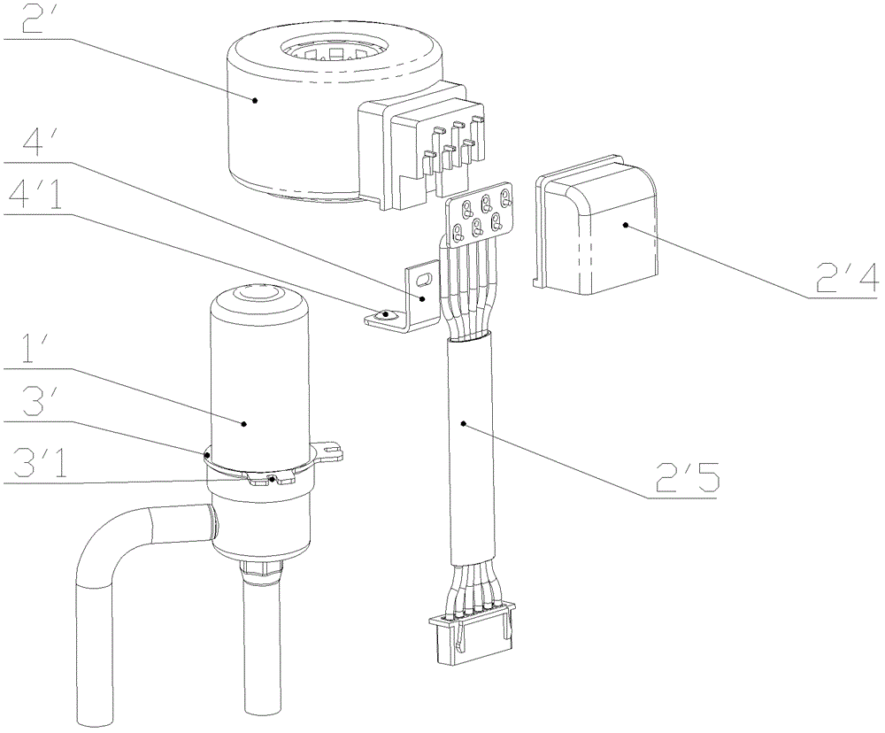
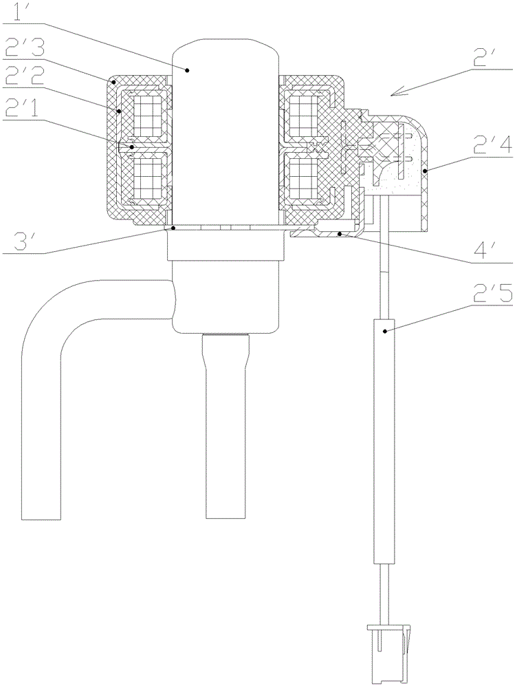
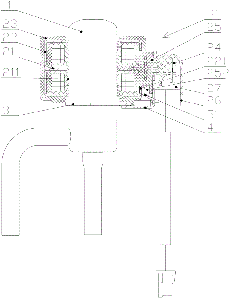
[0041] Please refer to image 3 , Figure 3-1 with Figure 3-2 , image 3 It is a schematic structural diagram of the electronic expansion valve in the first embodiment of the present invention; Figure 3-1 for image 3 Processing and assembly flow chart of the coil of the electronic expansion valve; Figure 3-2 for image 3 Processing flow chart of the buckle and transition part of the middle coil.

[0042] In the basic technical scheme of the presen...


PUM


Abstract

The invention discloses an electronic expansion valve which comprises a valve body (1) and a coil (2), wherein the coil (2) is connected with a buckle (4) conductively connected with the valve body (1), the coil (2) comprises an electromagnetic polar plate (21), a stator housing (22) which is in conductive contact with the electromagnetic polar plate (21) and a non-conductive plastic housing (23) wrapped on the outer part of the stator housing (22), the buckle (4) is in further conductive contact and connection with a transition part, and the transition part is in conductive contact with the stator housing (22). Due to the adoption of a structure design, the electronic expansion valve can ensure that parts inside the coil (2) are grounded, therefore, the coil (2) can be prevented from being damaged due to a high-voltage or ultra-high voltage electric signal.

Description

technical field [0001] The invention relates to the technical field of refrigerant fluid control components, in particular to an electronic expansion valve. Background technique [0002] The stepping motor direct-acting electronic expansion valve is another basic part of the four basic parts of the refrigeration system except the evaporator, compressor and condenser, and is the key part to adjust the flow of the system. The stepping motor direct-acting electronic expansion valve includes two parts: a coil and a valve body, wherein the valve body is equivalent to the rotor part of the stepping motor, and the coil is equivalent to the stator part of the stepping motor. The signal, the claw pole of the magnetic conductor of the coil produces a regular magnetic field movement, which drives the rotation of the rotor inside the valve body to adjust the flow rate at the valve port of the valve body, thereby realizing the regulation and control of the flow rate in the system. The e...

Claims


Application Information

Patent Timeline
Patent Type & Authority Patents(China)
IPC IPC(8): F16K31/06
Inventor 不公告发明人
Owner ZHEJIANG SANHUA INTELLIGENT CONTROLS CO LTD
Why Eureka
Try Eureka