Silencer for exhaust system of gasoline engine

A gasoline engine and exhaust system technology, applied to engine components, machines/engines, noise reduction devices, etc., can solve the problems of large metal vibration, insufficient noise reduction, and loud noise, so as to keep the airflow soft and stable, eliminate kinetic energy and Effect of reducing vibration and exhaust noise

Active Publication Date: 2015-05-27
肇庆市高要区康成五金有限公司
View PDF7 Cites 0 Cited by
  • Summary
  • Abstract
  • Description
  • Claims
  • Application Information

AI Technical Summary

Problems solved by technology

Although the muffler has a certain noise reduction effect, the exhaust gas running path formed by the muffler of this structure is not reasonable, resulting in insufficient noise reduction, and cannot effectively reduce the kinetic energy of the airflow, so that the noise reduction effect is not obvious; and the airflow directly Impacting the metal makes the metal vibrate greatly, resulting in greater noise caused by the metal vibration
At the same time, the structure of the muffler is relatively complicated, and the muffler used to achieve the same noise reduction effect is relatively large in size and high in cost
With the increase of motor vehicle speed, the existing mufflers cannot effectively improve the noise pollution caused by the operation of gasoline engines, and need to be continuously improved.

Method used


Image

  • Silencer for exhaust system of gasoline engine
  • Silencer for exhaust system of gasoline engine
  • Silencer for exhaust system of gasoline engine

Examples


Embodiment 1

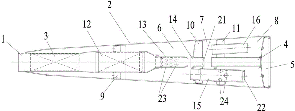
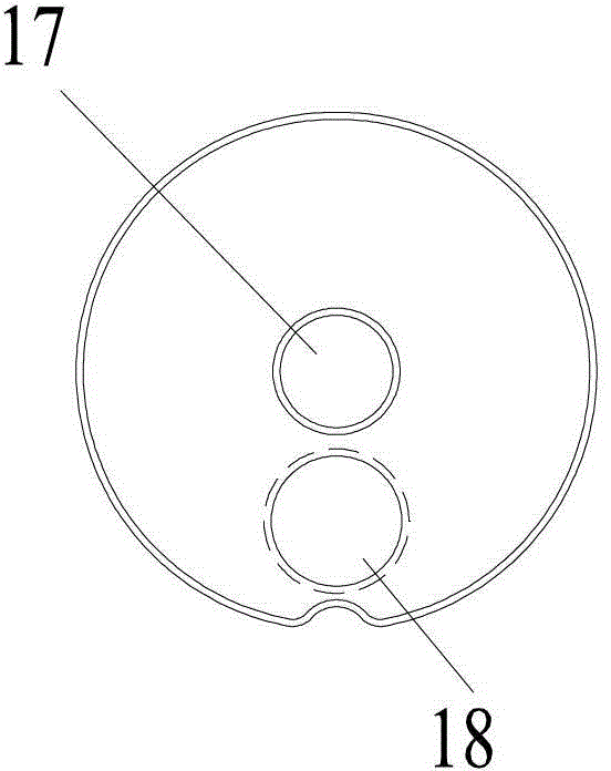
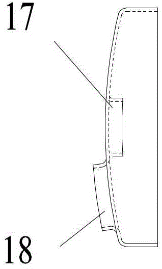
[0037] The structure schematic diagram of Embodiment 1 of the muffler used in the gasoline engine exhaust system of the present invention is as follows figure 1 As shown, the muffler includes a front exhaust pipe 1, a muffler cylinder 2, a catalytic converter 3 arranged in the muffler cylinder 2, a muffler assembly, a tailpipe 4 and a tail cover 5 connected in sequence; wherein, the muffler assembly It includes a one-hole plate 9, a two-hole plate 10 and a three-hole plate 11 which divide the muffler cylinder 2 into the first cavity 6, the second cavity 7 and the third cavity 8 in sequence, a connecting pipe 12, and the pipe wall is set There are a first-level porous pipe 13 with several second muffler holes 23 , a first-level muffler pipe 14 , a second-level muffler pipe 15 and a draft pipe 16 . The connecting pipe 12 is inserted on a hole plate 9, one end on one side of the hole plate 9 is connected to the tail end of the catalytic converter 3, and the other end on the other...

Embodiment 2

[0046] This embodiment differs from Embodiment 1 in that:

[0047] (1) The present invention is used for the structure schematic diagram of the muffler embodiment two of gasoline engine exhaust system as Image 6 As shown, the second-level muffler pipe 15 is located on the wall of the third cavity 8 and is provided with a first muffler hole 24, and the first muffler hole 24 in this embodiment is a side facing the tailpipe 4 The openings on the wall, the first muffler hole 24 can not only make the gas discharged to the third chamber 8 after canceling each other in the secondary muffler pipe 15, and the discharged air flow impacts the round pipe surface of the tail pipe 4, which can Diverging, buffering and softening the airflow, avoiding the impulsive airflow impacting the tailpipe round tube surface at the same time, forming a sequential dispersion and impacting the tailpipe round tube surface, thereby reducing the metal noise emitted by the impact.

[0048] (2) Image 6 The...

Embodiment 3

[0051] The difference between this embodiment and Embodiment 1 is that the first silencing hole is not provided on the secondary silencing pipe. Cavity, and one end arranged in the third cavity is not provided with a blocking cover one, and the two ends of the secondary muffler pipe are open ends. Other structures of the muffler in this embodiment are the same as those of the muffler in Embodiment 1.

[0052] The muffler in this embodiment works like this: the engine airflow enters the first-stage porous pipe from the tail end of the catalytic converter through the connecting pipe, the airflow discharged from the first-stage porous pipe enters the first-stage muffler pipe for consumption, and a part of the pulsed airflow hits first The wall of the first-stage muffler pipe and the second cover consume part of the kinetic energy. At this time, the pulsed airflow rebounding toward the air intake direction is constantly opposed to another part of the pulsed airflow rushing towards...


PUM


Abstract

The invention provides a silencer for an exhaust system of a gasoline engine. A silencing assembly of the silencer comprises a one-hole tray, a two-hole tray, a three-hole tray, a connecting pipe, a first-stage porous pipe, a first-stage silencing pipe, a second-stage silencing pipe and a guide pipe, wherein the one-hole tray, the two-hole tray and the three-hole tray divide a silencer cylinder into a first cavity, a second cavity and a third cavity; the first-stage silencing pipe is arranged in the two-hole tray in a penetration manner, one end of the first-stage silencing pipe is opened and is arranged in the first cavity to be opposite to an exhaust end of the first-stage porous pipe, and the other end of the first-stage silencing pipe is arranged in the second cavity and is provided with a blanking cap II to form a blind end; the second-stage silencing pipe is arranged on the two-hole tray and the three-hole tray in a penetration manner to communicate the first cavity and the second cavity; and the guide pipe and a tail pipe are both arranged on the three-hole tray, one ends of the guide pipe and the tail pipe are opened and are both arranged in the second cavity, the other end of the guide pipe is arranged in the third cavity, and the other end of the tail pipe is an exhaust end which is arranged outside the silencer cylinder. The silencer disclosed by the invention can be used for depleting kinetic energy and damping vibration of airflow stage by stage so as to effectively reduce the noise during exhaust.

Description

technical field [0001] The present invention relates to a mechanical muffler, and more particularly to a muffler for a gasoline engine exhaust system. Background technique [0002] During the exhaust gas exhausting process of a gasoline engine, the pressure of the exhaust gas will generate a continuous pulsed air flow at the outlet of the exhaust pipe. The pulsed gas rushes out of the exhaust port at high speed. Exhaust noise. Therefore, a motor vehicle generally needs to install a muffler on the engine exhaust pipe. The muffler is used to consume airflow energy, reduce the pressure of the airflow, and reduce noise. [0003] According to the principle of interference, the muffler has two basic muffler methods: absorption and reflection. The absorption muffler converts mechanical energy into heat energy through the friction of exhaust gas on sound-absorbing materials such as glass fiber, steel fiber and asbestos; the reflection muffler There are multiple harmonic chambers c...

Claims


Application Information

Patent Timeline
Patent Type & Authority Patents(China)
IPC IPC(8): F01N1/08
Inventor 杨富周陈良周陈忠起
Owner 肇庆市高要区康成五金有限公司
Why Eureka
Try Eureka