
Microarray die-free forming device based on surface acoustic wave and forming method

A technology of moldless molding and surface acoustic wave, which is applied in the field of micro-molding devices and molding, can solve the problems of restricting the development and application of rapid light-curing micro-molding methods, reducing production efficiency, etc., and achieve mature manufacturing processes, high production efficiency, and manufacturing low cost effect

Inactive Publication Date: 2013-04-03
ZHEJIANG UNIV
View PDF5 Cites 19 Cited by
  • Summary
  • Abstract
  • Description
  • Claims
  • Application Information

AI Technical Summary

Problems solved by technology

The application of rapid light-curing molding method to micro-molding manufacturing is an emerging micro-molding method. This molding technology belongs to material accumulation technology. Compared with traditional micro-manufacturing technology, this technology has higher material utilization rate, molding speed and precision. , so the use of light-curing molding method to manufacture surface micro-array structures has great advantages over traditional micro-manufacturing technology, but the point-by-point and layer-by-layer scanning curing method reduces its production efficiency and limits the development of rapid light-curing micro-molding methods and application

Method used


Image

  • Microarray die-free forming device based on surface acoustic wave and forming method
  • Microarray die-free forming device based on surface acoustic wave and forming method
  • Microarray die-free forming device based on surface acoustic wave and forming method

Examples


Embodiment Construction

[0031] The present invention will be further described below in conjunction with the accompanying drawings and embodiments.

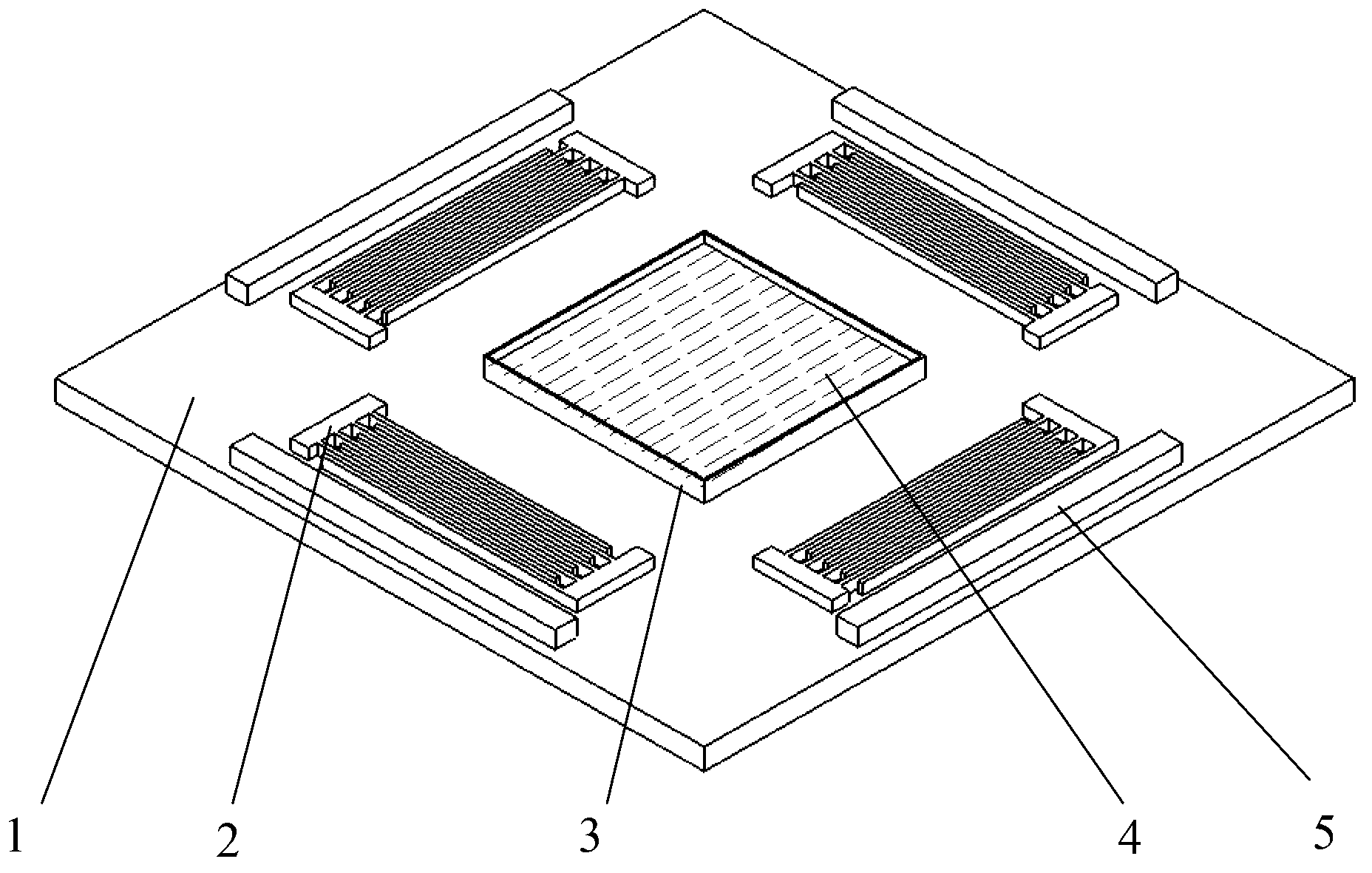
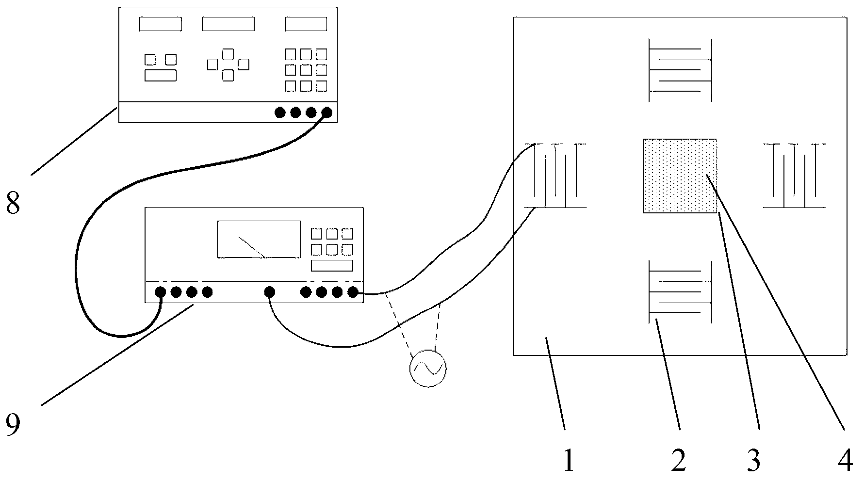
[0032] Such as figure 1 As shown, the present invention has two pairs of interdigital transducers 2 photolithographically etched on a square piezoelectric substrate 1, and each pair of interdigital transducers 2 is arranged symmetrically with the central axis of the square piezoelectric substrate 1 as the axis. A square glass liquid tank 3 is placed in the middle of the piezoelectric base plate 1 and cemented with the piezoelectric base plate 1 , and the formed liquid material 4 is placed in the glass liquid tank 3 .

[0033] The square glass liquid tank 3 is a bottomless glass liquid tank, and its glass wall surface is bonded to the square piezoelectric substrate plate 1. The formed liquid material 4 contained in the glass liquid tank 3 has a thickness less than or equal to 5mm.

[0034] The side length of the square molten glass tank 3 is less than o...


PUM


Abstract

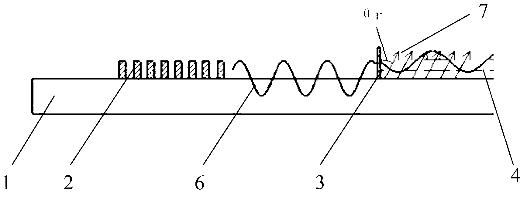
The invention discloses a microarray die-free forming device based on a surface acoustic wave and a forming method. The technical scheme is that a square piezoelectric matrix plate is provided with two pairs of interdigital transducers in a photoetching manner, each pair of interdigital transducers is symmetrically arranged with a center shaft of the square piezoelectric matrix plate as an axis, a square glass fluid tank is placed in the middle of the piezoelectric matrix plate and adhered to the piezoelectric matrix plate, and a formed liquid-state material is accommodated in the glass fluid tank. An ultrasonic surface wave is transmitted in the piezoelectric matrix plate, the energy of the ultrasonic surface wave is leaked into the formed liquid-state material within a certain angles to form a sound field, a signal generator and a power amplifier are adjusted to change amplitude values, frequency and phases of the ultrasonic surface wave, so that a required stable microarray structure is formed on the surface of the formed liquid-state material, and the microarray structure is cured and formed through ultraviolet irradiation. The microarray die-free forming device based on the surface acoustic wave and the forming method have the advantages that the sound field is adopted to manufacture the surface microarray structure through rapid forming in the liquid-state material, the die is not required, the manufacturing process is simple, the equipment requirement is low, the operation is simple and convenient, the production cost is low, and the material usage rate and the production efficiency are high.

Description

technical field [0001] The invention relates to a micro-molding device and a molding method, in particular to a micro-array moldless molding device and a molding method based on surface acoustic waves. Background technique [0002] With the advancement of science and technology, products continue to develop towards miniaturization. As a multi-disciplinary research field, microsystems integrate mechanics, electronics, materials, mechanics and other disciplines, and are widely used in biomedicine, aerospace, electronic information and other fields, especially the development and application of micro-electromechanical systems (MEMS) has opened up a New technological fields and industries. As an important part of microsystems, tiny components have always been a research hotspot in their molding and manufacturing methods. The microarray structure refers to the structure with tiny bosses or corrugated arrays on the surface. Due to its special surface microarray morphology, it ha...

Claims


Application Information

Patent Timeline
IPC IPC(8): B29C67/00B29C35/08
Inventor 梅德庆梁灵威姚喆赫孟坚鑫范宗尉杨克己陈子辰
Owner ZHEJIANG UNIV
Learn More