Automatic chamfering machine

A chamfering machine and automatic technology, applied in the field of machining, can solve the problems of low efficiency, low precision, troublesome positioning, etc., and achieve the effect of high degree of automation, improving work efficiency and reducing labor costs.

Inactive Publication Date: 2013-04-03
上海华测先越材料技术有限公司
View PDF5 Cites 7 Cited by
  • Summary
  • Abstract
  • Description
  • Claims
  • Application Information

AI Technical Summary

Problems solved by technology

In the existing technology of chamfering the workpiece, there are problems such as troublesome positioning, low precision and low efficiency

Method used


Image

  • Automatic chamfering machine
  • Automatic chamfering machine
  • Automatic chamfering machine

Examples


Embodiment Construction

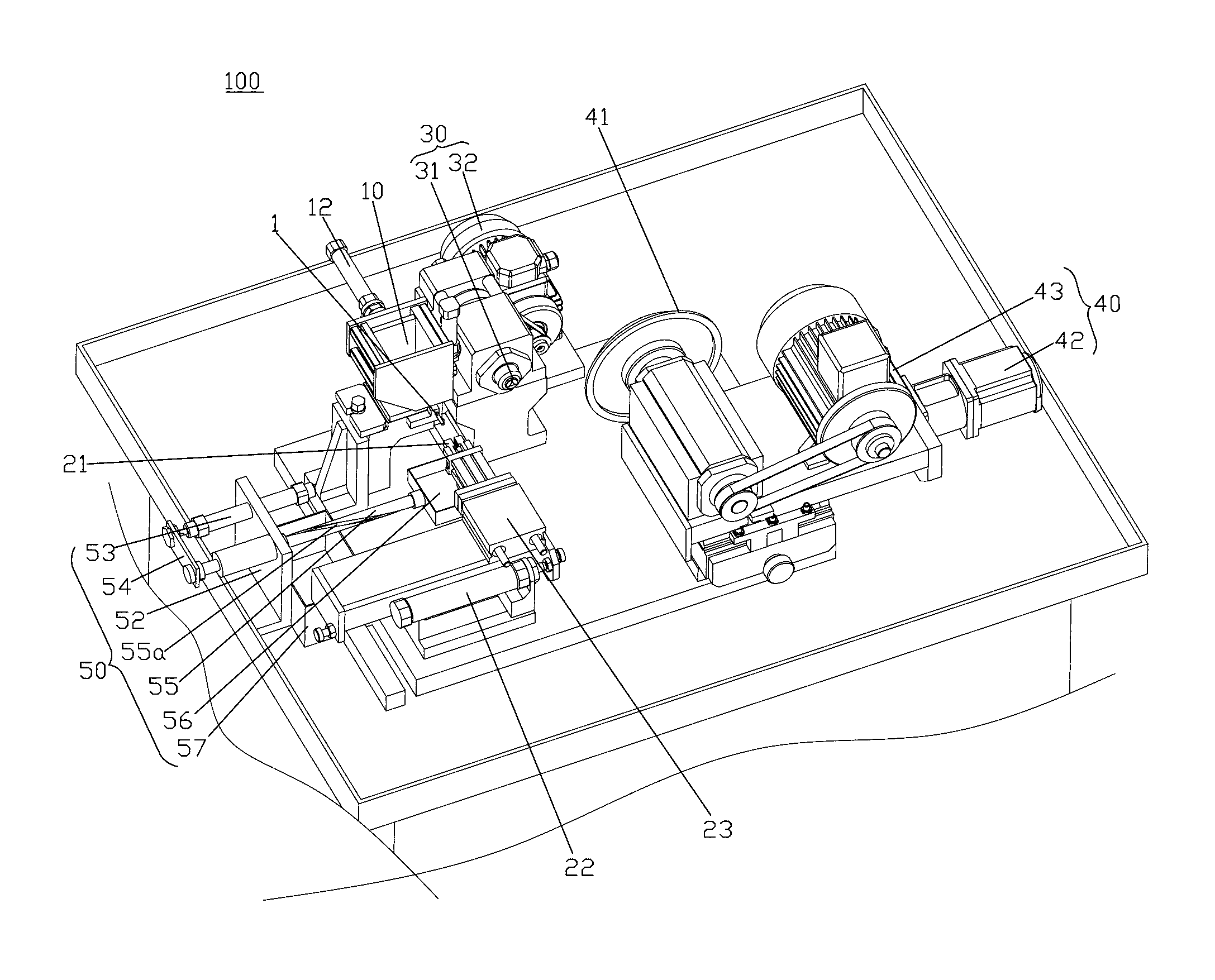
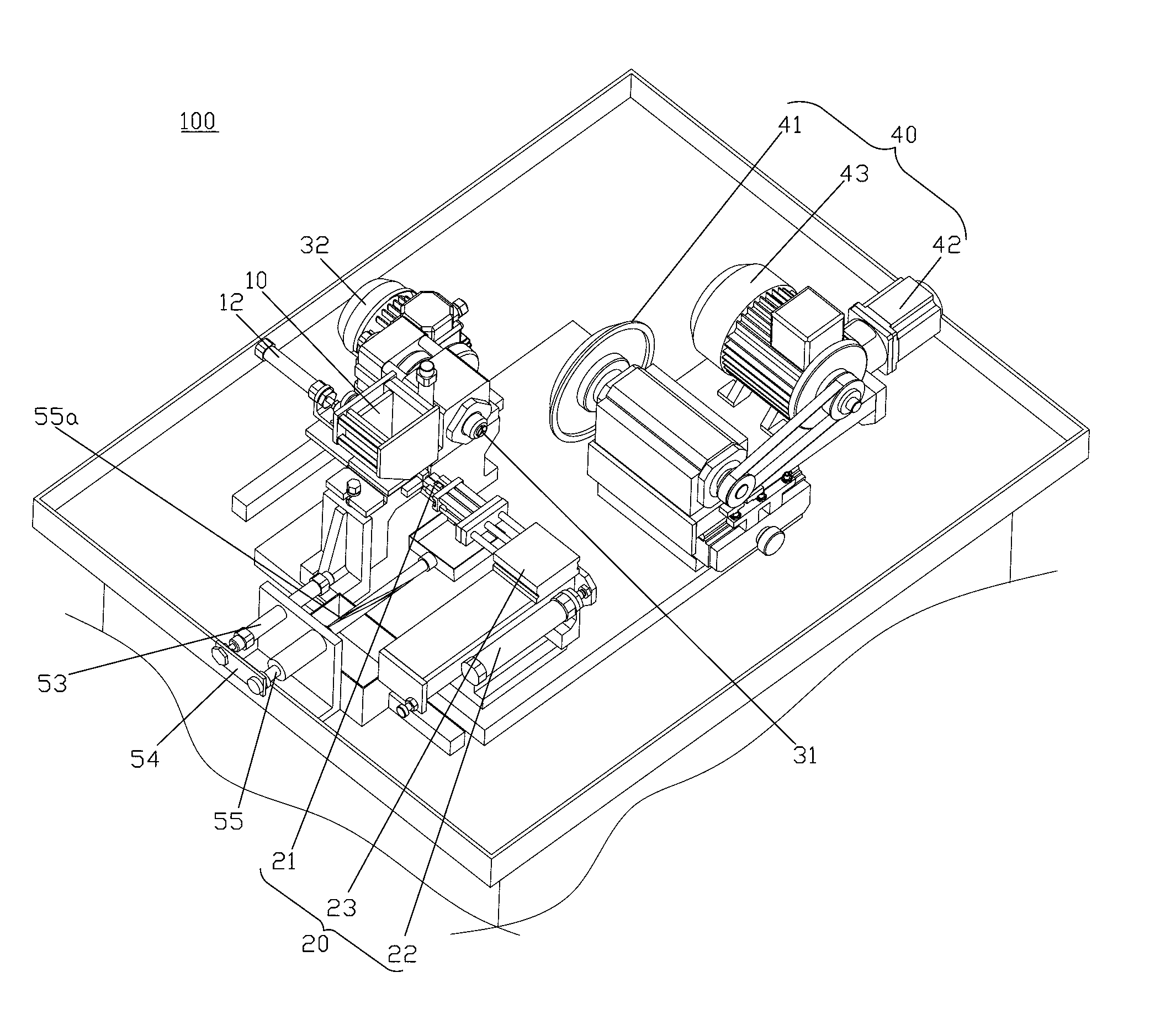
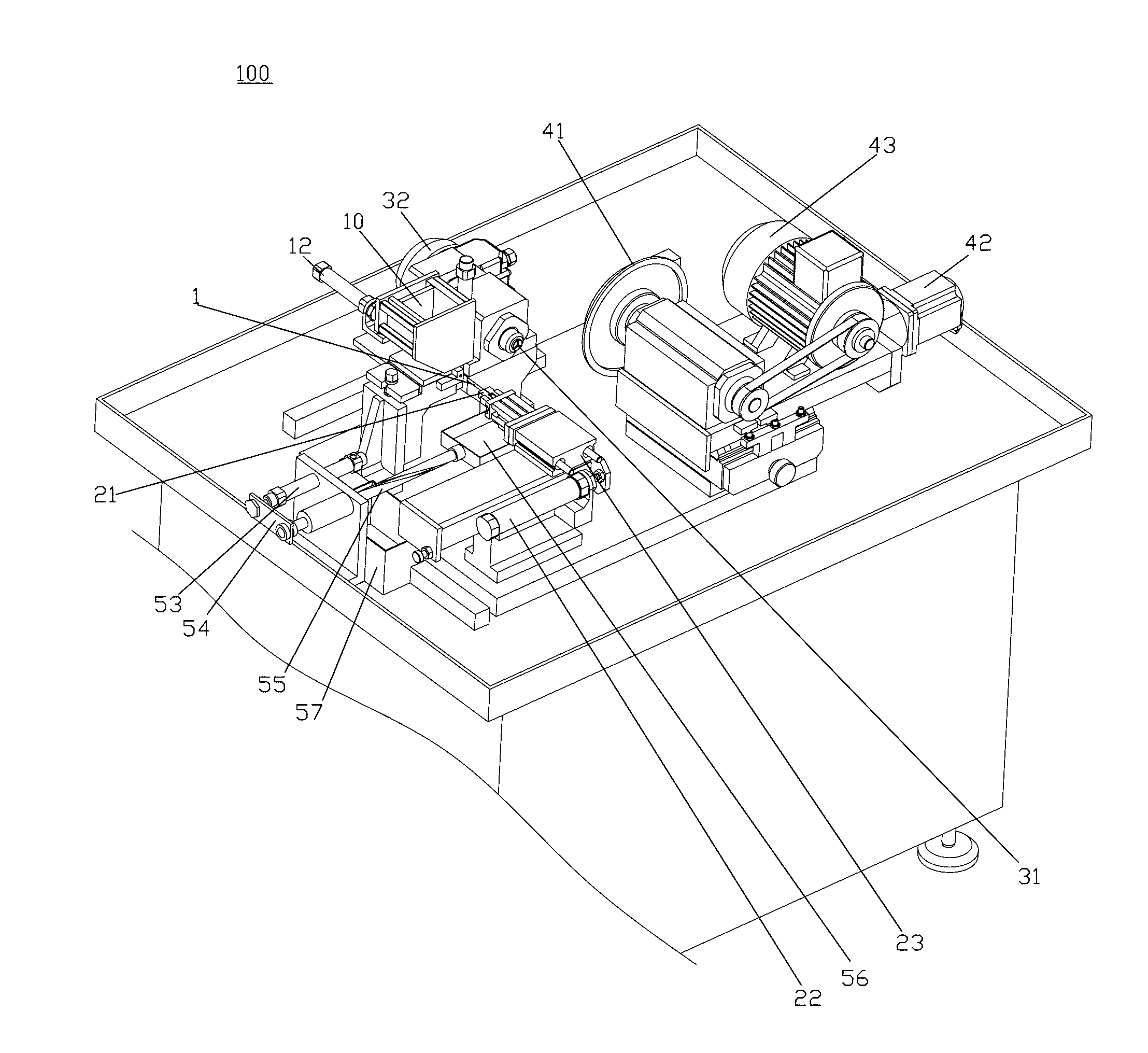
[0024] Embodiments of the present invention will now be described with reference to the drawings, in which like reference numerals represent like elements. As mentioned above, such as Figure 1-5 As shown, the automatic chamfering machine 100 provided by the present invention is used for chamfering cylindrical workpieces, including: feeding trough 10, transfer mechanism 20, clamping device 30 and grinding disc device 40, in the layout of an embodiment , the transfer mechanism 20 and the grinding disc device 40 are arranged on one side, and the feeding trough 10 and the clamping device 30 are arranged on the other side.

[0025] The feed trough 10 is in the shape of an inverted pyramid with a large top and a small bottom, and a groove (not shown in the figure) that just accommodates a workpiece 1 is provided at the bottom. The workpiece 1 to be processed is placed in the feed trough 10, and the bottom is There is a discharge port (not shown in the figure) for the extraction of...


PUM


Abstract

The invention discloses an automatic chamfering machine. A discharging port for drawing out a workpiece is formed at the bottom of a feeding groove. A handover mechanism comprises clamp jaws, a first lateral sliding mechanism and a first longitudinal sliding mechanism, wherein the clamp jaws can be driven to align at the workpiece through the fit sliding of the first lateral sliding mechanism and the first longitudinal sliding mechanism, draw the workpiece out of the feeding groove and convey the workpiece to a clamp device. The clamp device comprises telescopic fastening heads and a rotating mechanism. When the workpiece is conveyed to the clamp device by the clamp jaws, the telescopic fastening heads retract after holding the workpiece and then fasten and fix the workpiece. The workpiece is driven by the rotating mechanism to rotate through the telescopic fastening heads. An abrasive disc device comprises an abrasive disc, a second lateral sliding mechanism and a driving device arranged on the second lateral sliding mechanism, wherein the abrasive disc is arranged on the driving device, pushed by the second lateral sliding mechanism to approach and/or depart from the workpiece, and driven by the driving device to rotate and carry out chamfering processing on the workpiece. The automatic chamfering machine disclosed by the invention can realize automatic feeding, clamping, fixing and chamfering.

Description

technical field [0001] The invention relates to the field of mechanical processing, in particular to an automatic chamfering machine capable of automatically chamfering and stacking cylindrical workpieces. Background technique [0002] In the field of mechanical processing, it is often necessary to chamfer the workpiece. When chamfering the workpiece, it is necessary to position the workpiece, and then move the grinder to chamfer the positioned workpiece. In the prior art of chamfering a workpiece, there are problems such as troublesome positioning, low precision and low efficiency. [0003] In order to improve chamfering accuracy, improve work efficiency and reduce costs, it is necessary to develop an automatic chamfering machine capable of automatic feeding, clamping and chamfering. Contents of the invention [0004] The object of the present invention is to provide an automatic chamfering machine capable of automatic feeding, clamping and fixing and chamfering. [000...

Claims


Application Information

Patent Timeline
Patent Type & Authority Applications(China)
IPC IPC(8): B24B9/00
Inventor 陈益思陈军董宁李波郭冰
Owner 上海华测先越材料技术有限公司
Why Eureka
Try Eureka