
Onboard pod body for helicopter

A technology for helicopters and cabins, applied in the fields of machinery, heat and electromagnetics, can solve the problems that the surface of the cabin is not easy to make smooth, it is difficult to meet the heat dissipation requirements, and the assembly workload is large, so as to achieve light weight, not easy to lose stability, and structural stability. good stiffness effect

Active Publication Date: 2015-02-04
CNGC INST NO 206 OF CHINA ARMS IND GRP
View PDF5 Cites 1 Cited by
  • Summary
  • Abstract
  • Description
  • Claims
  • Application Information

AI Technical Summary

Problems solved by technology

The problem existing in the middle structure of the existing domestic electronic pod is that there is a transition member connection between the airborne electronic equipment cabinet and the skin of the truss structure
If the middle structure of the existing domestic electronic pod is adopted, it is difficult to meet the heat dissipation requirements through exhaust cooling
[0005] The number of connecting rivets in the middle section of the existing domestic electronic pod is large, and the assembly workload is large. At the same time, it also increases the stress concentration and the weakening of the cross-sectional area of ​​the wall plate by the nail holes, and the surface of the cabin is not easy to make smooth; when the skin is affected In the case of axial pressure, it is prone to instability

Method used


Image

  • Onboard pod body for helicopter
  • Onboard pod body for helicopter
  • Onboard pod body for helicopter

Examples


Embodiment Construction

[0032] Now in conjunction with embodiment, accompanying drawing, the present invention will be further described:

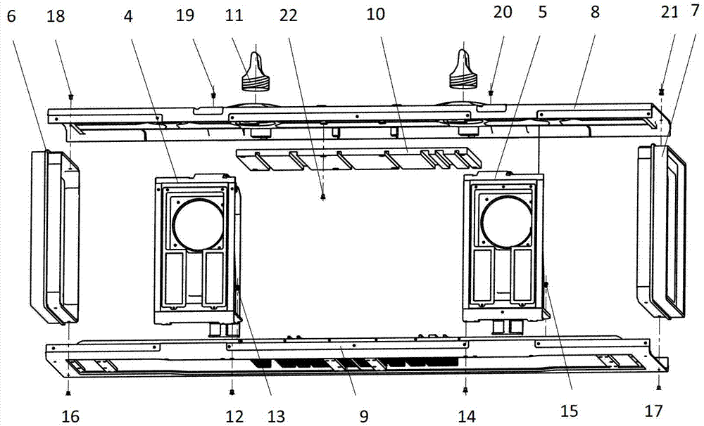
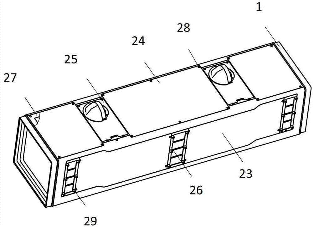
[0033] During design, the left middle frame and the right middle frame are arranged in the stop area, and two end frames are designed for the installation port of the radome; the upper and lower skins and ribs are integrated, and the overall longitudinal wall plate is processed from the same material— The top plate and the cold plate; the slot plate and the top plate are screwed into a combined longitudinal wall plate; the lifting lugs are designed according to GJB 1B-95. The frame, cold plate, combined longitudinal wall plate and lifting lug constitute the skeleton of the cabin body to bear the load together.

[0034] With reference to above-mentioned accompanying drawing, the specific embodiment of the present invention is described in detail:

[0035] see figure 1 , during design, the left middle frame 4 and the right middle frame 5 are respectively arranged...


PUM


Abstract

The invention relates to an onboard pod body for a helicopter. The onboard pod body is characterized in that a top plate and a cold plate are fixed on and under a left-end frame, a right-end frame, a left-medium frame and a right-medium frame which are arranged in parallel to form a pod body, a plug in connector and a plug in box are arranged between the left-medium frame and the right-medium frame, two lifting lugs are arranged on the outer side of the top plate, lateral plates are arranged on two sides of the top plate 8 and the cold plate 9, a cold plate cover plate and an air inlet are arranged on the cold plate, the left-medium frame and the right-medium frame are provided with air ducts and externally provided with air outlets, through holes in which a cable penetrates are arranged in the left-medium frame and the right-medium frame, a closed space is arranged between the left-medium frame and the right-medium frame, and the air inlets penetrate through a cold plate air duct, and then penetrate through the medium frame air ducts to form a heat radiating channel together with an air outlet. According to the invention, by adopting technical schemes that an integral wallboard structure is adopted in the top plate and the cold plate, a pod body framework, an environment control system and onboard electronic device cabinet are integrally designed, and the environment control system is isolated from the electronic device, the technical problems of low requirements of rigidity, strength, better heat radiation and protection, and the like are solved.

Description

technical field [0001] The invention belongs to the three technical fields of machinery, heat and electromagnetics, and relates to a helicopter airborne pod cabin body, which is equipped with environmental temperature control and electromagnetic compatibility of the helicopter, airborne suspended objects, and airborne electronic equipment. Background technique [0002] The electronic pod has the advantages of independent structure, easy maintenance and expansion, and relatively simple interface with the carrier aircraft. The electronic pod is used as the platform, and the airborne radar jamming pod can be added to the carrier aircraft to meet the tactical mission requirements as needed. [0003] The middle cabin of the existing domestic electronic pod is riveted into the cabin skeleton by the main load-bearing frame, surrounding frame, long truss or truss beam and connecting angle pieces, and finally the skin is riveted on the outer surface of the cabin skeleton to form a la...

Claims


Application Information

Patent Timeline
Patent Type & Authority Patents(China)
IPC IPC(8): B64D47/00
Inventor 庞利娥刘继鹏
Owner CNGC INST NO 206 OF CHINA ARMS IND GRP
Learn More