
Projection optical system

A projection optical system and light beam technology, applied in the field of projection optical systems, can solve problems such as small numerical aperture, large wave aberration RMS and distortion, short object-space working distance and image-space working distance, and achieve large numerical aperture and reduced Processing, the effect of reducing the number of lenses

Inactive Publication Date: 2015-01-28
INST OF OPTICS & ELECTRONICS - CHINESE ACAD OF SCI
View PDF4 Cites 0 Cited by
  • Summary
  • Abstract
  • Description
  • Claims
  • Application Information

AI Technical Summary

Problems solved by technology

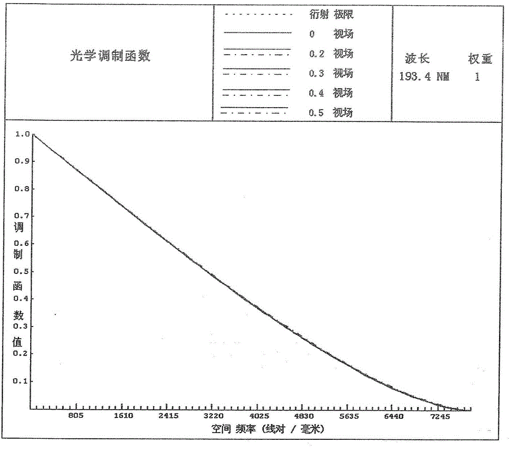
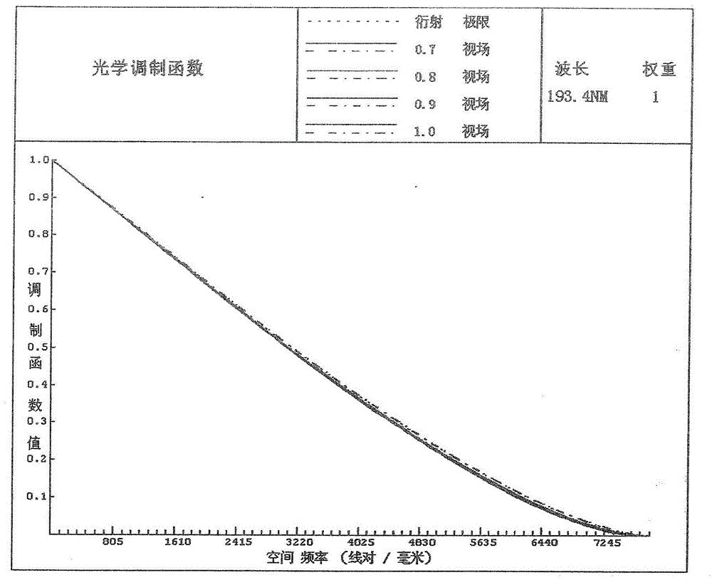
[0005] In order to solve the problems of too many lenses in the projection optical system, large wave aberration RMS and distortion, small numerical aperture, and too short object-space working distance and image-space working distance in the existing technical solutions, the purpose of the present invention is to provide a A projection optical system with fewer lenses, smaller wave aberration RMS and distortion, and larger numerical aperture

Method used


Image

  • Projection optical system
  • Projection optical system
  • Projection optical system

Examples


Embodiment Construction

[0030] In order to better illustrate the purpose and advantages of the present invention, the specific implementation manners of the present invention will be further described below in conjunction with the accompanying drawings.

[0031] figure 1 It is a structural schematic diagram of the projection optical system of the present invention. The projection optical system is used to project the pattern in the object plane onto the image plane. The first lens group G1, the second lens group G2, and the third lens are arranged along the optical axis direction of the projection optical system. Group G3, the fourth lens group G4 and the fifth lens group G5, and the first lens group G1, the second lens group G2, the third lens group G3, the fourth lens group G4 and the fifth lens group are on the same optical axis, from The order of the incident direction of the light beam is that the first lens group G1 has negative refractive power, the second lens group G2 has positive refractive...


PUM

PropertyMeasurementUnit
wavelengthaaaaaaaaaa
refractive indexaaaaaaaaaa

Abstract

The invention provides a projection optical system. A first lens group, a second lens group, a third lens group, a fourth lens group, and a fifth lens group are sequentially arranged along the direction of an optical axis of the projection optical system and located on the same optical axis. The first lens group and the third lens group are provided with negative focal power. The second lens group, the fourth lens group and the fifth lens group are provided with positive focal power. The first lens group receives input light beams and outputs first divergent beams; the second lens group receives the first divergent beams and output second divergent beams; the third lens group receives the second divergent beam and output first convergent beams; the fourth lens group receives the first convergent beams and outputs third divergent beams; and the fifth lens group receives the third divergent beams, outputs second convergent beams, and converges the second convergent beams to an image surface. On the condition of high resolutions and high numerical apertures, the projection optical system effectively reduces the number of lenses, reduces cost of processing, detecting and adjusting, and provides relatively large object space and image space working distances at the same time.

Description

technical field [0001] The invention relates to a projection optical system in a photolithography system, in particular to a high-resolution projection optical system. Background technique [0002] Since the advent of the integrated circuit IC in the 1970s, it has experienced a development stage from small-scale to ultra-large-scale, and its progress has benefited from the rapid development of lithography. Photolithography is one of the most important processes in the manufacture of large-scale integrated circuits. The exposure equipment used in lithography accurately projects the pattern on the mask onto the silicon wafer coated with photoresist through the projection optical system in a step-by-step repeating or scanning manner. Exposure is carried out, and the quality of the exposure has a great influence on the subsequent development, etching, and glue removal processes. With the development of integrated circuit manufacturing, the resolution requirements of the project...

Claims


Application Information

Patent Timeline
Patent Type & Authority Patents(China)
IPC IPC(8): G02B13/18G02B13/14G03F7/20
Inventor 冉英华邢廷文张海波吕保斌陈红丽白瑜
Owner INST OF OPTICS & ELECTRONICS - CHINESE ACAD OF SCI
Learn More