
Ultrasonic imaging post-processing method and device thereof

A post-processing device, ultrasonic imaging technology, applied in radio wave measurement systems, instruments, etc., can solve the problems of high computing resources, storage resources, complexity, and high frequency of processing data, reducing storage resources, easy to implement, computing small amount of effect

Inactive Publication Date: 2013-03-20
INST OF ACOUSTICS CHINESE ACAD OF SCI
View PDF6 Cites 11 Cited by
  • Summary
  • Abstract
  • Description
  • Claims
  • Application Information

AI Technical Summary

Problems solved by technology

[0005] The existing ultrasonic imaging post-processing basically adopts the Hilbert method. The length of the filter used in this method is generally long, and the computing resources and storage resources occupied during implementation are relatively high, and the power consumption used during processing is relatively high. Ideal for real-time processing
The cascaded integral comb filter structure of the prior art is used in the software radio in the communication field, but there is no record of applying this filter to the field of ultrasound imaging in the ultrasound imaging system
[0006] In the ultrasound imaging system, the signal frequency after front-end processing is relatively high, and transmission and storage are relatively difficult. It is necessary to reduce the data rate after quadrature down-demodulation and down-sampling
However, the frequency of data processing is high, and the implementation has a certain degree of complexity. The present invention proposes an implementation method for this problem. This method is suitable for real-time processing and is very effective for data processing.

Method used


Image

  • Ultrasonic imaging post-processing method and device thereof
  • Ultrasonic imaging post-processing method and device thereof
  • Ultrasonic imaging post-processing method and device thereof

Examples


Embodiment Construction

[0041] The method is described below with reference to the accompanying drawings. In the drawings, the same or similar components are denoted by the same reference numerals even though they are depicted in different drawings.

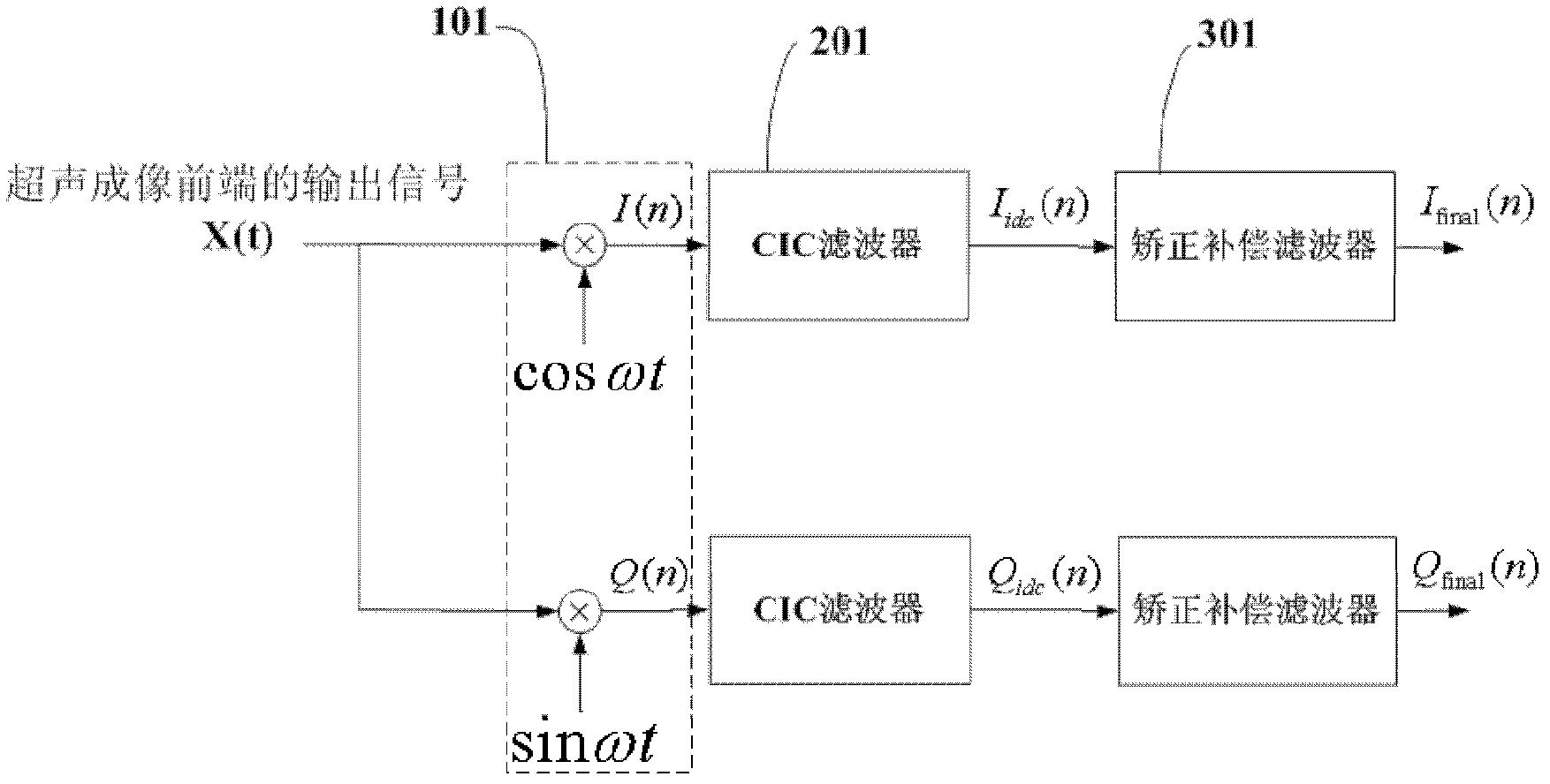
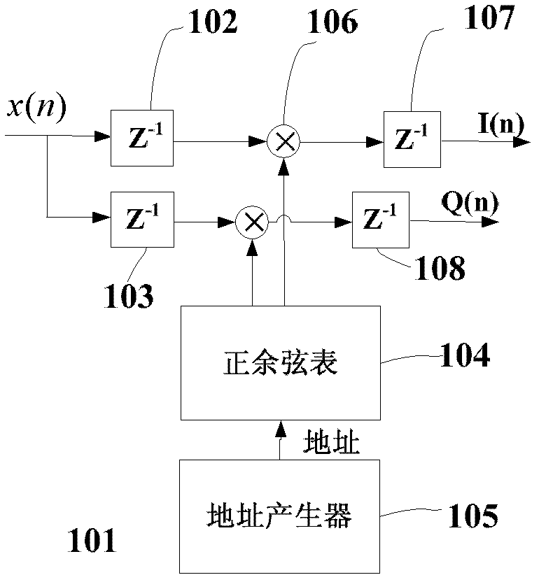
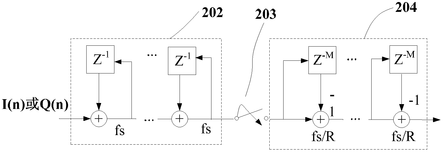
[0042]In order to achieve the above object, the present invention adopts the following technical solution. The whole method includes firstly obtaining the quadrature I and Q components of the high-speed ultrasonic signal by frequency mixing. Then use the cascaded integral comb filter to low-pass filter the two orthogonal signals. At the same time, because the sampling rate of the final output signal frequency is 4-8 times lower than the original ultrasonic imaging sampling rate, the cascaded integral comb downsampling in the middle of the filter. Because the cascaded integral comb filter is essentially a low-pass filter, the transition band of the frequency response of the cascaded integral comb filter is not very ideal, and the correction filter is us...


PUM


Abstract

The invention relates to an ultrasonic imaging post-processing method and a device of the ultrasonic imaging post-processing method. The ultrasonic imaging post-processing method is used for processing output signals of the front end of the ultrasonic imaging beam forming and comprises the following steps: (1) conducting mixing processing to the output signals of the front end of the ultrasonic imaging and an orthogonality I component and an orthogonality component Q are acquired, (2) conducting lowpass filtering processing to two line orthogonal signals through a cascading integral comb filter and meanwhile conducting down-sampling in the middle of cascading integral comb filter. The ultrasonic imaging post-processing method further comprises steps of revising a transitional zone of frequency response of the cascading integral comb filter through a correcting filter. The step (2) further comprises the following steps:(1) sending the orthogonality I component and the orthogonality Q component after the mixing processing into the cascading integral comb filter and an output signal Ii (n) and an output signal Qi (n) are acquired, (2) conducting down-sampling to the signal Ii (n) and the output signal Qi (n) according to post-processing requirements to the signal Iid (n) and the output signal Qid (n), (3) processing Iid (n) and Qid (n) through the cascading integral comb filter and an output signal Iiedc (n) and an output signal Qidc (n) of the cascading integral comb filter are acquired.

Description

technical field [0001] The invention belongs to the technical field of ultrasonic imaging, and in particular relates to an ultrasonic imaging processing realization technology, in particular to an ultrasonic imaging post-processing method and device. Background technique [0002] The current ultrasonic imaging equipment mainly adopts the working mode of pulse echo, which uses the transducer array to transmit ultrasonic narrow pulses, the transducer array receives the signal, and then improves the signal strength of the scattering target through focused beamforming, and the signal after beamforming passes through Orthogonal demodulation and down-conversion to obtain the envelope and other processing, and finally sent to the imaging display system. At present, researchers at home and abroad are focusing on real-time performance, miniaturization, low power consumption and low cost of equipment. The miniaturization of equipment is conducive to the use of ultrasonic imaging equi...

Claims


Application Information

Patent Timeline
IPC IPC(8): G01S7/52
Inventor 吴文焘吕燚汪东李平肖灵
Owner INST OF ACOUSTICS CHINESE ACAD OF SCI
Learn More