
Deburring machine tool

A deburring and machine tool technology, which is applied to the parts of grinding machine tools, grinding machines, and machine tools suitable for grinding the edge of workpieces, etc. It can solve the problems that affect the quality of parts reprocessing and difficult to remove burrs, and achieve the goal of improving work efficiency. Effect

Inactive Publication Date: 2013-03-13
SUZHOU POLYTECHNIC INST OF AGRI
View PDF5 Cites 21 Cited by
  • Summary
  • Abstract
  • Description
  • Claims
  • Application Information

AI Technical Summary

Problems solved by technology

[0003] In the process of invention and creation, the inventor found that there is at least such a problem: some burrs are difficult to remove, which affects the quality of parts and reprocessing

Method used


Image

  • Deburring machine tool
  • Deburring machine tool
  • Deburring machine tool

Examples


Embodiment Construction

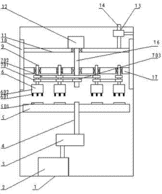
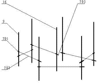
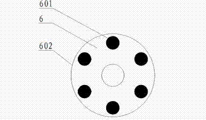
[0028] The present invention will be described in further detail below in conjunction with the accompanying drawings.

[0029] figure 1 Shown is a schematic structural view of the deburring machine tool of the present invention, including a casing 1, a first working disk 5 is built inside the casing 1, the first working disk 5 is fixedly connected to the first driving shaft 4, and the first driving shaft 4 is connected to the On the first motor 2, a number of workpiece clamping discs 501 are evenly distributed on a circle of the upper surface of the first working disc 5, and there is also a horizontal position above the first working disc 5 that is connected to the inside of the casing 1 and whose vertical position is adjustable. The second working disk 17, the lower surface of the second working disk 17 is equipped with a number of rotatable brushes 6, the brushes 6 include a number of brush filaments 601 and a clamping cylinder 602 for clamping the brush filaments 601, t...


PUM


Abstract

The invention discloses a deburring machine tool which comprises an enclosure, a first working disk and a second working disk, wherein the first working disk and the second working disk are arranged inside the enclosure; the first working disk is arranged below the second working disk; the upper surface of the first working disk is provided with a plurality of workpiece clamping disks; the second working disk is driven to rotate by a driving device; and a plurality of rotatable brushes are also arranged below the second working disk. By the rotation of the brushes, burrs can be effectively removed and the adverse effects on the size, which are generated in the process of deburring by conventional mechanical methods such as a turning method and a milling method are avoided.

Description

technical field [0001] The invention relates to a deburring device for mechanical parts. Background technique [0002] Most of the mechanical parts are formed by stamping. On the exit side of the tool, there will be burrs to varying degrees, which will affect the quality of further processing. In the prior art, physical polishing is usually used to remove burrs for some small parts, while for large and irregular parts, mechanical methods such as grinding and cutting are generally used to remove these brushes, because metals generally have certain plasticity and burrs It will fall back and forth with the movement of the abrasive tool, and some will be broken, leaving sharp edges and corners, while some will be embedded in tiny grooves, and the burrs embedded in the tiny grooves will reappear during reprocessing. [0003] In the process of invention and creation, the inventor found that there is at least such a problem: some burrs are difficult to remove, thus affecting the...

Claims


Application Information

Patent Timeline
Patent Type & Authority Applications(China)
IPC IPC(8): B24B9/00B24B41/06B24B47/12
Inventor 时忠明
Owner SUZHOU POLYTECHNIC INST OF AGRI
Learn More