
Microwave heating device and application thereof

A microwave heating device, microwave device technology, applied in the chemical/physical/physicochemical process of applying energy, refining to remove heteroatoms, etc., can solve the industrial production of microwave heating devices that are difficult to scale and cannot be used to realize chemical reactions Process, no clear instructions and other issues, to achieve good operational safety, uniform distribution of microwave field, good sealing effect

Inactive Publication Date: 2014-09-03
CHINA UNIV OF PETROLEUM (BEIJING) +1
View PDF4 Cites 0 Cited by
  • Summary
  • Abstract
  • Description
  • Claims
  • Application Information

AI Technical Summary

Problems solved by technology

However, this technology has the following problems: it is recorded that crude oil and catalyst are mixed by stirring, but in fact it is difficult to mix oil, gas and catalyst evenly in the cavity, and this mixing is difficult in the actual operation process. It is also easy to block the pipeline; in this method, after the hydrodesulfurization reaction is completed, the catalyst and the crude oil need to be separated, and the operation is cumbersome through gravity sedimentation or filtration; in addition, the microwave device is a batch reactor, and the supply body has many limit
Among them, the purpose of avoiding the leakage of combustible gas is achieved by opening holes on the safety isolator (in fact, the leaked gas is emitted through these holes), however, how to prevent hydrogen or combustible fuel gas from entering, this document does not make clear instructions , and the leakage of hydrogen is absolutely prohibited for the oil hydrogenation reaction, and there are potential safety hazards
[0010] In summary, the microwave heating devices reported in the above prior art are difficult to apply to large-scale industrial production, let alone realize chemical reaction processes that require continuous input and output of reactants into microwave heating chambers

Method used


Image

  • Microwave heating device and application thereof
  • Microwave heating device and application thereof
  • Microwave heating device and application thereof

Examples


Embodiment 1

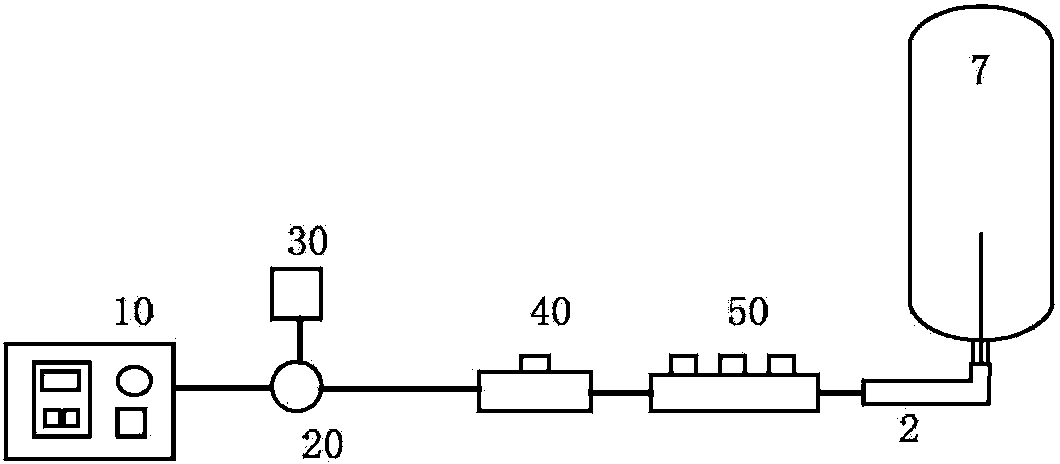
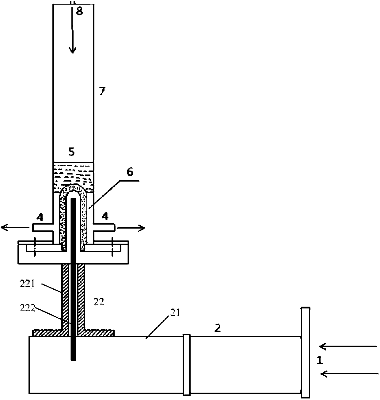
[0042] See figure 1 As shown, the microwave heating device of this embodiment includes a microwave source 10, a circulator 20, a water load 30, a directional coupler 40, a three-pin automatic regulator 50, a waveguide 2, and a microwave reactor 7 in the order of microwave conduction. see you again figure 2 The detailed structure of the shown waveguide section (according to those known in the art, microwave source, circulator, water load, directional coupler, and three-pin automatic adjuster are also directly connected by waveguide, and only shown in the figure as this A key feature of the invention is the structure of the waveguide section after the three-pin auto-adjuster according to the waveguide transmission sequence), wherein the waveguide 2 includes a rectangular waveguide 21 (the rectangular waveguide can also be a circular waveguide) and a coaxial waveguide 22, and The axial waveguide includes a coaxially arranged metal shell 221 (cylindrical) and a probe 222 (slende...


PUM

PropertyMeasurementUnit
diameteraaaaaaaaaa
heating valueaaaaaaaaaa

Abstract

The invention provides a microwave heating device and an application thereof. The microwave heating device comprises a microwave reactor and a microwave generation and transmission device, wherein the microwave generation and transmission device comprises a microwave source, a circulator, a water load, a directional coupler, a three-dowel automatic regulator and a waveguide in a microwave conduction sequence, in the waveguide section, a rectangular waveguide or a circular waveguide is converted into a coaxial transmission manner, and a probe stretches forwards to the interior of the microwave reactor from one end of the microwave reactor so as to feed microwaves into the microwave reactor. According to the microwave heating device disclosed by the invention, microwaves in the reactor are uniform in distribution, and the microwave heating device is good in sealability and can be feasibly applied to any reactions utilizing microwaves for heating.

Description

technical field [0001] The invention relates to a microwave heating device and its application, in particular to a microwave heating reaction device and the application of the device. Background technique [0002] Microwave has obvious characteristics such as short wavelength (1m~1mm), high frequency (300MHz~300GHz), and quantum characteristics. The basic principles of microwave heating are the conduction of charged particles and the polarization of dielectrics. The ion conduction mechanism means that the ions in the medium generate migration current in the electromagnetic field to generate heat. The dielectric polarization mechanism refers to that under the action of an electromagnetic field, polar molecules change from a random distribution state to a polar alignment according to the electromagnetic field. Under the action of microwave high-frequency electromagnetic field, these orientation movements are constantly changing according to the frequency of alternating elect...

Claims


Application Information

Patent Timeline
Patent Type & Authority Patents(China)
IPC IPC(8): B01J19/12C10G45/02
Inventor 商辉赵金岷刘植昌张海超
Owner CHINA UNIV OF PETROLEUM (BEIJING)
Learn More