
Furnace having even distribution of gas

A reduction furnace and gas technology, which is applied in the field of equipment for preparing molten iron, can solve the problems of uneven distribution of reducing gas and the inability to be supplied to the center of the reduction furnace, etc., and achieve facility capacity, uniform reduction rate, and improved operation rate Effect

Inactive Publication Date: 2013-02-27
POHANG IRON & STEEL CO LTD +1
View PDF4 Cites 1 Cited by
  • Summary
  • Abstract
  • Description
  • Claims
  • Application Information

AI Technical Summary

Problems solved by technology

[0007] An aspect of the present invention made to solve the problems in the prior art aims at eliminating the uneven distribution of the reducing gas (wherein the reducing gas supplied to the inside of the reducing furnace cannot be supplied to the center of the reducing furnace, but It mainly flows along the wall) to increase the reduction rate of the charge in the reduction furnace and make the reduction rate among the particles of the charge uniform, thereby reducing the heat load of the furnace when the charge is supplied to the furnace, thereby achieving such things as increased production, Lower fuel costs, higher operating rates and improved operational stability

Method used


Image

  • Furnace having even distribution of gas
  • Furnace having even distribution of gas

Examples


Embodiment Construction

[0033] Hereinafter, embodiments of the present invention are described in detail with reference to the accompanying drawings.

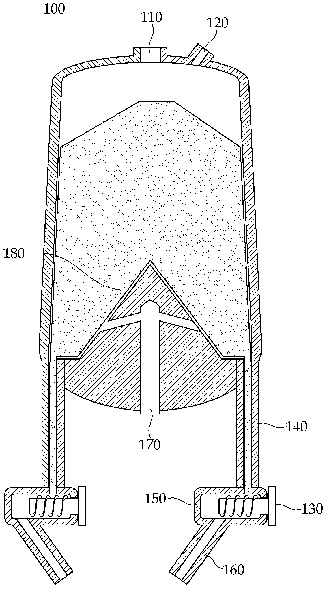
[0034] figure 2 is a longitudinal sectional view of a reduction furnace 100 according to an embodiment of the present invention. refer to figure 2 , the upper part of the reduction furnace 100 is provided with a burden input port 110 and a plurality of exhaust gas discharge ports 120 . A lower end inside the reduction furnace 100 is provided with a convex pile 180 (or a concave pile, these two terms are used interchangeably hereinafter). The protruding stakes 180 are provided to prevent the charge from bursting fire or the formation of a fixed layer caused by the load of the charge itself. The reducing gas blowing port 170 is provided at the bottom of the boss 180 , and a path is formed inside the boss 180 to allow the reducing gas blown through the reducing gas blowing port 170 to pass through. The reducing gas blowing port 170 is formed at the...


PUM


Abstract

The present invention relates to a furnace for reducing ore containing an iron oxide component, comprising a charge inlet port (110) into which a charge is inserted, and a reduced gas intake port (170) into which reduced gas is blown, wherein the charge inlet port (110) is formed on the upper portion, and the reduced gas intake port (170) is provided at the center of the lower portion. According to the present invention, the reduced gas can be distributed evenly by blowing the reduced gas into the center of the lower portion of the furnace, thereby increasing the reduction rate of the charge inside the furnace and rendering a uniform reduction rate between the particles of the charge.

Description

technical field [0001] The present invention relates to a reduction furnace for reducing ore containing iron oxide components, and an apparatus for producing molten iron by melting the reduced ore. Background technique [0002] figure 1 A conventional reduction furnace for reducing ore containing iron oxide components, and an apparatus 1 for producing molten iron by melting the reduced ore are shown. Such as figure 1 As shown in , the equipment 1 is equipped with a reduction furnace 10 for reducing or preheating agglomerated ore (such as pellets or lumpy ore, etc.) by blowing a reducing gas. The charge is charged into the reduction furnace 10 through the charge inlet 11 . The charge material reduced in the reduction furnace 10 is quantitatively discharged through the discharge screw 13 , and the discharged charge material is supplied to the melting furnace 20 through the vertical downcomer 14 and the inclined downcomer 16 . The vertical downcomer 14 is provided with a st...

Claims


Application Information

Patent Timeline
Patent Type & Authority Applications(China)
IPC IPC(8): C21B13/02
CPCC21B13/02C21B13/143C21B2100/44C21B2100/64F27B1/005F27D3/16F27D7/00
Inventor 姜信明李相皓
Owner POHANG IRON & STEEL CO LTD
Learn More