


Quick Research
Generate reliable direction feasibility study reports for your R&D in just a few steps.

Technical Q&A
Discover and master advanced knowledge NOW. Basics, ideas, possibilities, all at once.

Find Solutions
As an expert in R&D theories, this can generate solutions to your technical problems instantly.

Evaluate Feasibility
Analyze your overall solution with one click, know your potential R&D risks in advance.

Monitor Landscape
Get weekly tech updates, stay abreast of the latest tech innovations and key insights.
Pre-filled wire stirring friction welding method
A technology of friction stir welding and welding method, which is applied in the direction of welding equipment, non-electric welding equipment, metal processing equipment, etc., can solve the problem of thinning of the effective thickness of the weld, and achieve the reduction of the effective thickness of the weld and increase the welding speed , Increase the effect of weld reinforcement
- Summary
- Abstract
- Description
- Claims
- Application Information
AI Technical Summary
Problems solved by technology
Method used
Image

Examples
specific Embodiment approach 1
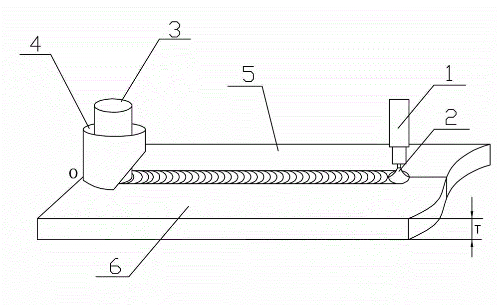
[0011] Specific implementation mode one: combine Figure 1 ~ Figure 3 Describe this embodiment, the prefilled wire friction stir welding method of this embodiment is realized according to the following steps:
[0012] Step 1. Clamping the workpiece to be welded: the first workpiece to be welded 5 and the second workpiece to be welded 6 are docked and placed in the same horizontal plane, and clamped on the workbench with a clamp. The first welded workpiece 5 and the second workpiece 6 to be welded are metal plates;
[0013] Step 2. Welding of the initial section of the prefilled wire: place the welding torch 1 at the initial position O of the joint between the two workpieces to be welded, and use TIG or MIG welding to weld along the first workpiece 5 to be welded and the second workpiece 6 to be welded Welding with pre-filled wire in the direction of welding, the welding length is 10mm-100mm, the welding current is 10A-200A, the walking speed of the welding torch is 0.1m / min-1...
specific Embodiment approach 2
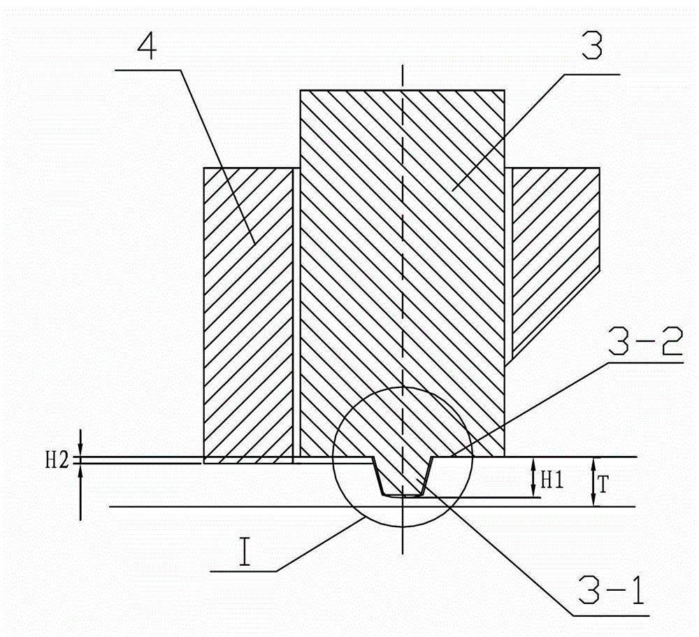
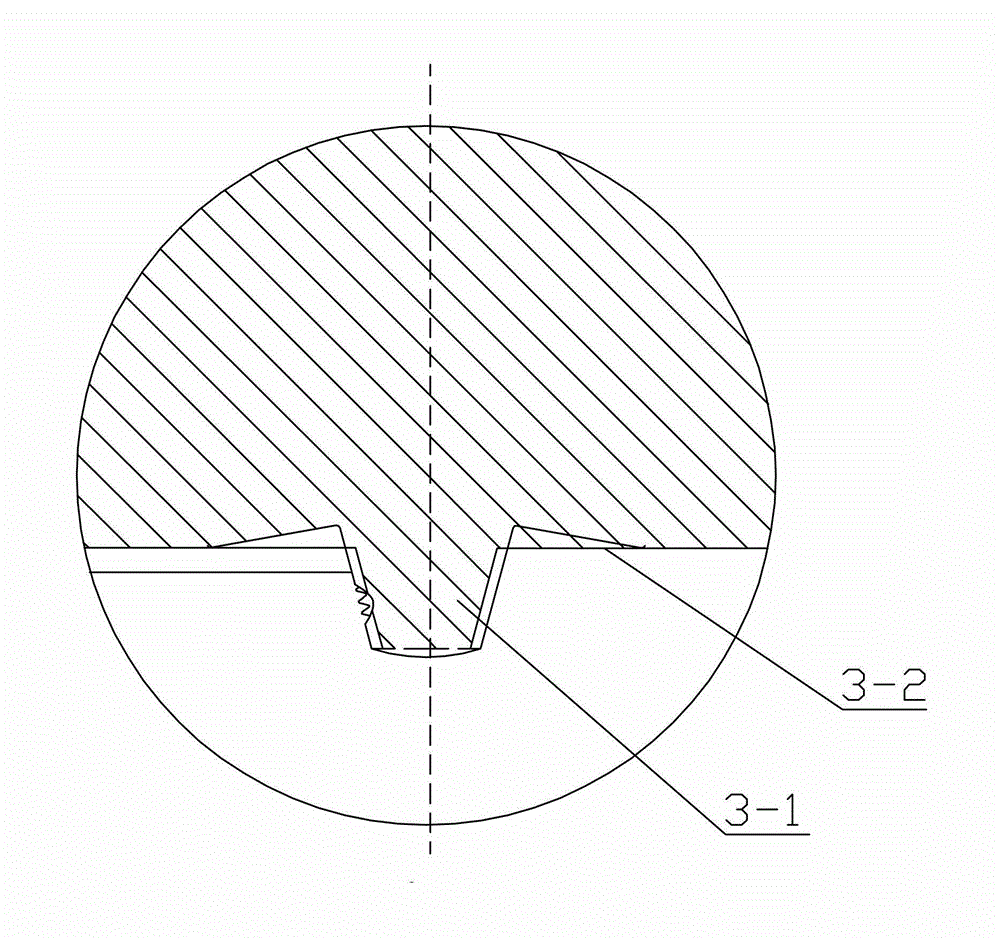
[0016] Specific implementation mode two: combination figure 2 To illustrate this embodiment, the depth of pressing the semi-cylindrical stationary shoulder sleeve 4 into the workpiece in step 3 of this embodiment is smaller than the depth of pressing the shoulder 3-2 into the workpiece. Other steps are the same as in the first embodiment.
specific Embodiment approach 3
[0017] Specific implementation mode three: combination figure 1 To illustrate this embodiment, the TIG or MIG pre-filled wire process in step 4 of this embodiment is performed synchronously with the friction stir welding process, and the welding position of the friction stir welding is located 10 mm to 100 mm behind the pre-filled wire arc 2 . Other steps are the same as in the first embodiment.
PUM
 Abstract
Description
Claims
Application Information
 - R&D Engineer
- R&D Manager
- IP Professional
- Industry Leading Data Capabilities
- Powerful AI technology
- Patent DNA Extraction
Browse by: Latest US Patents, China's latest patents, Technical Efficacy Thesaurus, Application Domain, Technology Topic, Popular Technical Reports.
© 2024 PatSnap. All rights reserved.Legal|Privacy policy|Modern Slavery Act Transparency Statement|Sitemap|About US| Contact US: help@patsnap.com