
Array flow velocity control valve structure suitable for incompressible fluid

A flow rate control and fluid compression technology, which is applied in the field of array flow rate control valve structure, can solve problems affecting the operation of on-site staff, bubble bursts, strong vibration of pipelines, etc., to facilitate online maintenance, reduce fluid kinetic energy, and reduce valve noise. Effect

Inactive Publication Date: 2013-02-20
WUXI SMART AUTO CONTROL ENG CO LTD
View PDF8 Cites 7 Cited by
  • Summary
  • Abstract
  • Description
  • Claims
  • Application Information

AI Technical Summary

Problems solved by technology

[0003] On the other hand, the bubbles generated by cavitation burst one after another, forming a wide frequency noise, which not only affects the operation of the on-site staff and the living environment of the surrounding residents, but also causes strong vibration of the pipeline, resulting in major safety accidents

Method used


Image

  • Array flow velocity control valve structure suitable for incompressible fluid
  • Array flow velocity control valve structure suitable for incompressible fluid
  • Array flow velocity control valve structure suitable for incompressible fluid

Examples


Embodiment Construction

[0030] The present invention will be further described below in conjunction with specific drawings.

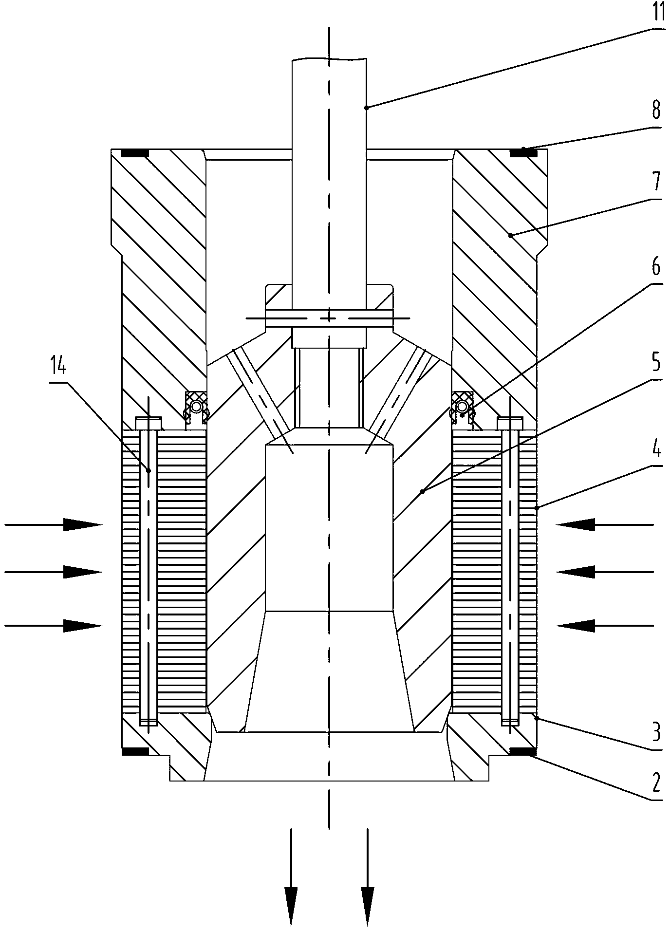
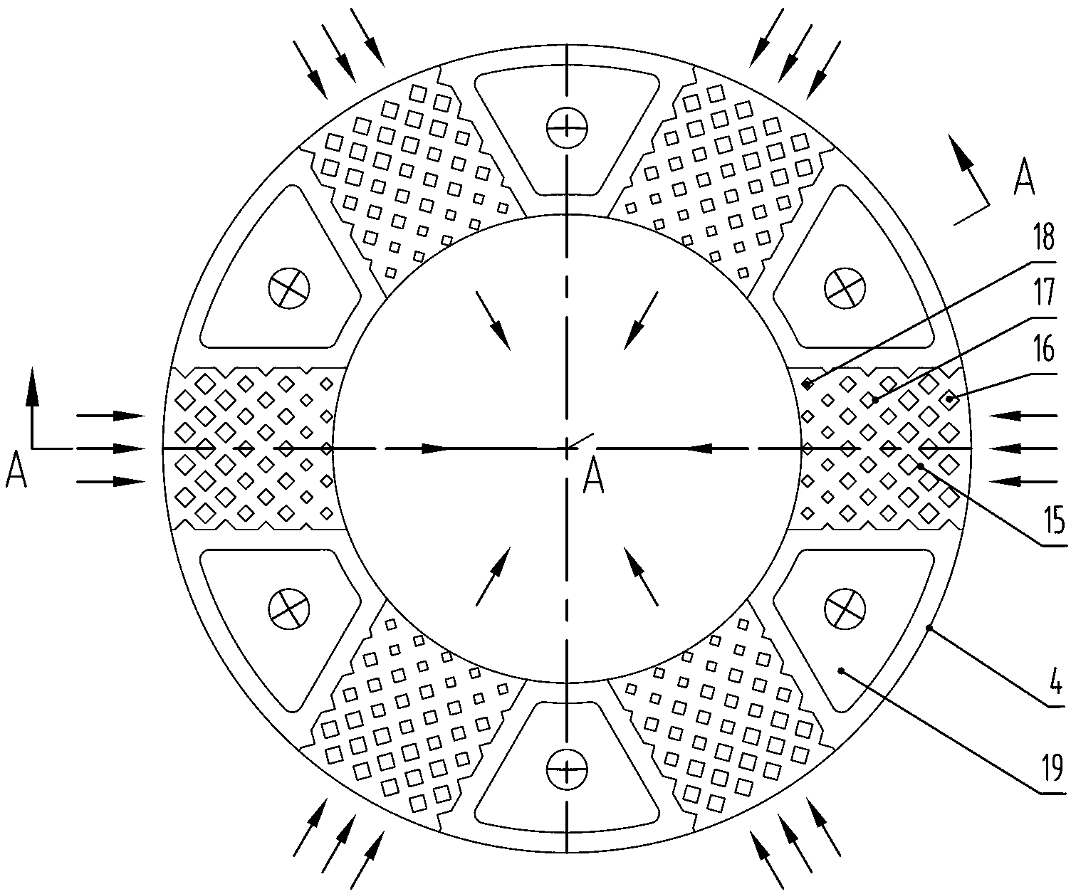
[0031] Such as Figure 1 ~ Figure 2 Shown: an array flow rate control valve structure suitable for compressible fluid, including valve body 1, sealing gasket 2, valve seat 3, throttle plate 4, valve core 5, balance sealing ring 6, guide seat 7, Gasket 8, gasket 9, upper cover 10, valve stem 11, stud 12, nut 13, positioning pin 14.

[0032] The present invention includes that a valve seat 3 is provided in the valve body 1 , and a sealing gasket 2 is used to seal between the valve seat 3 and the valve body 1 . Several throttle plates 4 are installed on the valve seat 3 , and the throttle plates 4 are positioned by positioning pins 14 . Each throttle plate 4 is composed of a parallel thin plate body 19 and a prism array structure 15, and the prism array structure 15 includes a large prism convex body 16, a prism convex body 17, and a small prism convex body 18. Wait for severa...


PUM


Abstract

The invention relates to an array flow velocity control valve structure suitable for incompressible fluid. The structure comprises a valve body, a valve base, valve cores, an upper cover and valve rods, wherein the base valve is arranged in the valve body, a plurality of throttle slices are arranged installed on the valve base, the throttle slices are positioned through positioning pins, each of the throttle slices comprises a parallel thin plate body and a rhombic pillar-shaped array structure, a guide base is installed on the throttle slices, balancing sealing rings are installed in the guide base, valve cores are installed in the throttle slices, the valve cores are connected with the valve rods, and the upper cover is installed on the valve body; and the upper cover is fixed on the valve body through a screw bolt and a nut. According to the structure, the fluid pressure is kept to be above the saturated vapor pressure, bubbles are avoided, and a cavitation phenomenon is eliminated; damages of inner parts of a valve, which are caused by energy blasting energy, are reduced; the valve is convenient to disassemble and clean, and on-line maintenance is facilitated; and the pressure is reduced step by step through flow rate control of high-speed incompressible fluid, the cavitation phenomenon is avoided, and the normal operation of the valve is guaranteed.

Description

technical field [0001] The invention relates to an array type flow rate control valve structure suitable for incompressible fluids, in particular to a flow rate control technology applied to control valves for liquids. Background technique [0002] In the field of liquid fluid control, when the liquid fluid with pressure P1 passes through the orifice of the control valve, the flow rate increases and the static pressure decreases. When the pressure P2 behind the orifice of the control valve is equal to or less than the working condition of the liquid fluid When the saturated vapor pressure Pv is lower, part of the liquid fluid will be vaporized into gas, forming a phenomenon of gas-liquid two-phase coexistence, which is called flash evaporation. When flashing occurs, the liquid fluid will erode the valve core, valve seat and other internal parts of the control valve, and affect the flow capacity of the valve. If after flashing occurs, P2 does not remain below the saturated v...

Claims


Application Information

Patent Timeline
Patent Type & Authority Applications(China)
IPC IPC(8): F16K1/00F16K1/36F16K1/42F16K47/08F16K47/02
Inventor 陈彦张程史强修刘玉萍
Owner WUXI SMART AUTO CONTROL ENG CO LTD
Learn More