An end cover for a racing differential
A differential and end cover technology, applied in the direction of differential transmission, belt/chain/gear, mechanical equipment, etc., can solve the problems of reducing the strength of the differential, oil leakage, etc., and achieve reliable connection and smooth torque transmission , the effect of avoiding the danger of oil leakage
Inactive Publication Date: 2015-07-29
SAIC-GM-WULING AUTOMOBILE CO LTD
View PDF11 Cites 0 Cited by
- Summary
- Abstract
- Description
- Claims
- Application Information
AI Technical Summary
Problems solved by technology
Drilling the bolt connection holes evenly distributed on the 9mm wide and very thin plane of the differential will reduce the strength of the differential to a certain extent and there is a risk of oil leakage
Method used
View moreImage
Smart ImageViewing Examples
Examples
Embodiment Construction
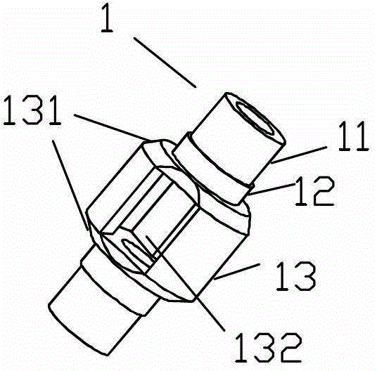
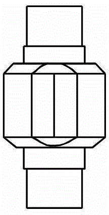
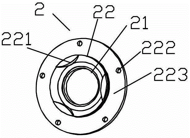
[0011] Such as Figure 1-5 As shown, the end cover of this racing differential, the racing differential 1 includes an upper end, a middle part, and a lower end, and the upper end includes a first cylinder 11 and a second cylinder with diameters D1 and D2 from top to bottom. Body 12, the middle part is a third cylinder 13 with a diameter D3, D1
Login to View More PUM
Abstract
The invention discloses an end cover of a differential mechanism of a racing automobile. The differential mechanism of the racing automobile comprises an upper end portion, a middle portion and a lower end portion. The upper end portion comprises a first cylinder with the diameter as D1and a second cylinder with the diameter as D2 from the top to the bottom, and the middle portion is provided with a third cylinder with the diameter as D3, wherein D1<D2<D3. Chamfers are arranged at the upper end and the lower end of the third cylinder, and three through grooves distributed evenly are arranged on a lateral wall of the third cylinder. The cross section of each through groove is a sector with the radius as r and chord height as h. The end cover comprises an upper shaft sleeve and a lower shaft sleeve, the inner diameters of the upper shaft sleeve and the lower shaft sleeve are respectively D4 and D3, wherein D4=D2=D3-2r+2h. Bosses attached to the three through grooves are arranged on an inner wall of the lower shaft sleeve, the cross section of each boss is a sector with the radius as r and chord height as h, and a plurality of bolt connecting holes are arranged at the position of an end face of the lower shaft sleeve close to an outer edge.
Description
technical field [0001] The invention relates to the technical field of racing cars, in particular to an end cover of a differential gear of a racing car. Background technique [0002] The differential used in the racing car is an irregular body with small ends and a large middle (such as Figure 1-3 As shown), the differential surface connected with other components through bolts is 19mm wide and only 9mm wide is flat and the rest are inclined surfaces with an outward inclination angle of 40 degrees, so that the characteristic surface accounts for two of all the connecting surfaces One-third, the narrowest connection surface of the other half of the connection surface is only 9mm wide and the wall thickness is only 3mm. Drilling the bolting holes evenly distributed on the 9mm wide and very thin plane of the differential will reduce the strength of the differential to a certain extent and there is a risk of oil leakage. Contents of the invention [0003] In order to overco...
Claims
Login to View More Application Information
Patent Timeline
Patent Type & Authority Patents(China)
IPC IPC(8): F16H48/38
Inventor 范健文刘琰陈春林岑延清黄海峰管菁
Owner SAIC-GM-WULING AUTOMOBILE CO LTD
- R&D Engineer
- R&D Manager
- IP Professional
- Industry Leading Data Capabilities
- Powerful AI technology
- Patent DNA Extraction
Learn More Browse by: Latest US Patents, China's latest patents, Technical Efficacy Thesaurus, Application Domain, Technology Topic, Popular Technical Reports.
© 2024 PatSnap. All rights reserved.Legal|Privacy policy|Modern Slavery Act Transparency Statement|Sitemap|About US| Contact US: help@patsnap.com