Two-end synchronous driving grinding method and headstock and tailstock special for grinder

A synchronous drive, grinding machine head technology, applied in the direction of grinding frame, grinding bed, grinding machine parts, etc., can solve the problems of workpiece bending deformation, unsuitable clamping force, low processing efficiency, etc., to eliminate Bending deformation, eliminating workpiece bending, good processing reliability

Inactive Publication Date: 2013-02-20
ANYANG XINSHENG MACHINE TOOL
View PDF7 Cites 0 Cited by
  • Summary
  • Abstract
  • Description
  • Claims
  • Application Information

AI Technical Summary

Problems solved by technology

[0002] The traditional grinding of long shaft and long screw parts generally adopts the method of clamping the workpiece with a chuck at one end and tightening the top at the other end. This method has the following disadvantages for grinding long shaft and long screw parts: One is that the workpiece will have a certain bending deformation due to improper clamping force during installation; the other is that there will be a large torsional deformation due to one end driving the workpiece during processing; the third is the disadvantage caused by the thermal deformation of the workpiece during processing The impact cannot be eliminated, and traditional machine tools cannot compensate
This is also the reason why the precision of screw grinding is relatively low and cannot meet the requirements.
For the grinding process of long screw, the numerical control rate of domestic machine tools is low, and the processing efficiency is not high.

Method used


Image

  • Two-end synchronous driving grinding method and headstock and tailstock special for grinder
  • Two-end synchronous driving grinding method and headstock and tailstock special for grinder
  • Two-end synchronous driving grinding method and headstock and tailstock special for grinder

Examples


Embodiment Construction

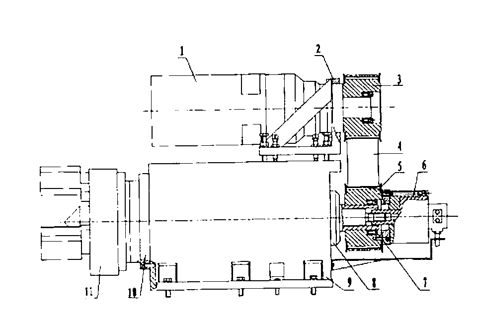
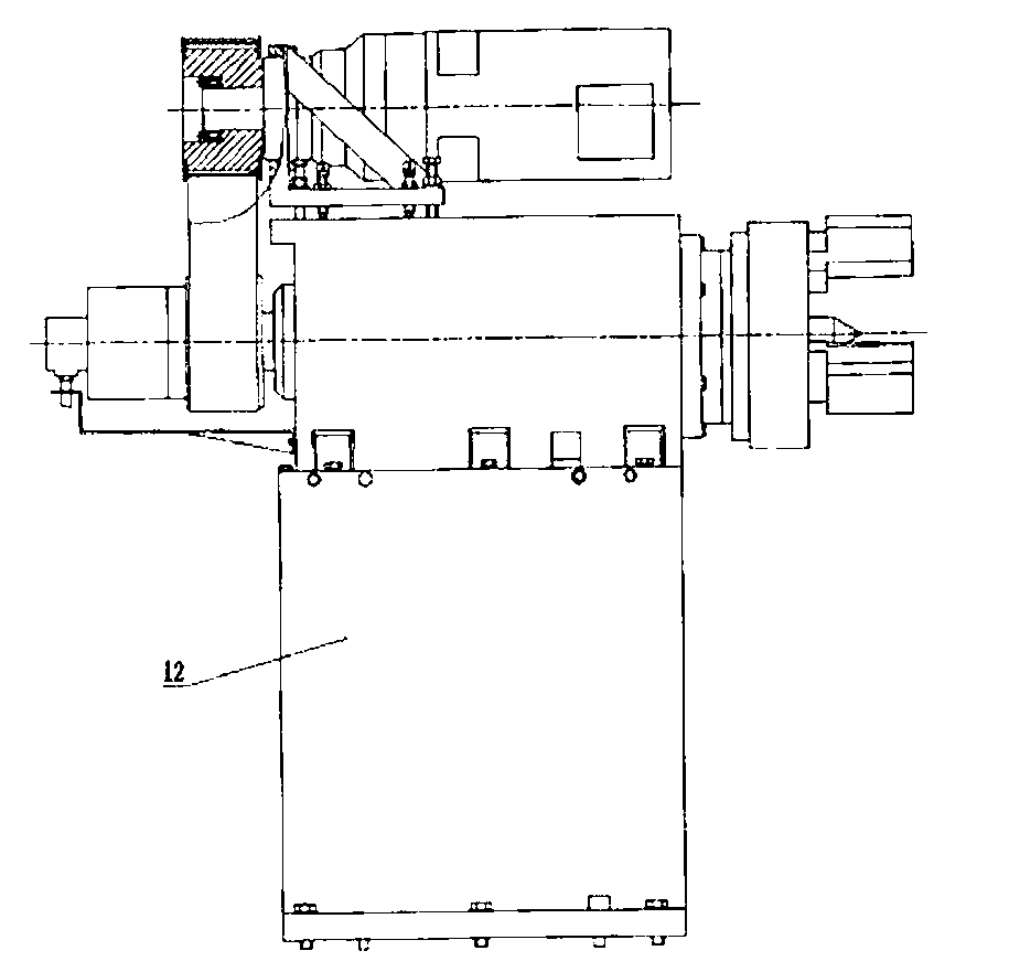
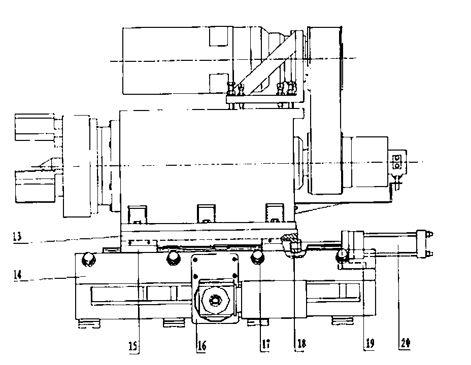
[0009] combine figure 1 , figure 2 , image 3 The details and working conditions of the present invention are described in detail. The headstock and tailstock of the grinding machine are equipped with the same set of spindle drive mechanism, and a reliable CNC control system is adopted. The spindle drive mechanism is equipped with a servo motor 1, and the end of the motor base 2 under the servo motor 1 is equipped with a synchronous pulley 3. One end of the main shaft case 9 is also equipped with a synchronous pulley 5, the synchronous belt 4 is installed between the synchronous pulley 2 and the synchronous pulley 5, the main shaft unit 10 is housed in the middle of the main shaft case 9, and the chuck 11 is installed on the main shaft unit 10 , an encoder 8 is installed on the main shaft unit 10, and an oil cylinder 6 is fixed through a flange 7 at one end of the synchronous pulley 5. The servo motor 1 drives the synchronous pulley 3 to rotate, and is transmitted to the s...


PUM


Abstract

The invention relates to a two-end synchronous driving grinding method and a headstock and a tailstock special for a grinder, and belongs to the field of machine tools. The technical scheme is that the headstock and the tailstock of the grinder are respectively provided with spindle driving mechanisms which are identical, a reliable numerical-control control system is adopted to control the two spindle driving mechanisms to rotate, each spindle driving mechanism is provided with a servo motor, and a synchronous pulley is arranged at one end of a motor base arranged below each servo motor. A synchronous pulley is also arranged at one end of a spindle box, a spindle unit is arranged in the middle of the spindle box, a compensation claw post-tensioning chuck and a coder are arranged on the spindle unit, a jacking oil cylinder is fixed on an oil cylinder base arranged on the tailstock, and a guide rail pair is arranged between a connection plate and a base of the tailstock. The two-end synchronous driving grinding method and the headstock and the tailstock special for the grinder have the advantages that synchronous driving of two ends of a workpiece is achieved through control and compensation of the control system, and harmful effects caused by torsion deformation, bending deformation and thermal deformation generated by one-end driving are removed. The headstock and the tailstock are novel in design, reasonable in structure, high in positioning accuracy and good in processing reliability.

Description

technical field [0001] The invention relates to a two-end synchronously driven grinding method, a special headstock and a tailstock for a grinding machine, and belongs to the field of machine tools, which can be applied to the grinding process of long shafts exceeding 10 meters and lead screw parts. Background technique [0002] The traditional grinding of long shaft and long screw parts generally adopts the method of clamping the workpiece with a chuck at one end and tightening the top at the other end. This method has the following disadvantages for grinding long shaft and long screw parts: One is that the workpiece will have a certain bending deformation due to improper clamping force during installation; the other is that there will be a large torsional deformation due to one end driving the workpiece during processing; the third is the disadvantage caused by the thermal deformation of the workpiece during processing The impact cannot be eliminated, nor can conventional ...

Claims


Application Information

Patent Timeline
Patent Type & Authority Applications(China)
IPC IPC(8): B24B47/12B24B41/02
Inventor 汪玉平李运生何爱国郭章信吕乐侯磊徐再云李根张澎王超
Owner ANYANG XINSHENG MACHINE TOOL
Why Eureka
Try Eureka