


Quick Research
Generate reliable direction feasibility study reports for your R&D in just a few steps.

Technical Q&A
Discover and master advanced knowledge NOW. Basics, ideas, possibilities, all at once.

Find Solutions
As an expert in R&D theories, this can generate solutions to your technical problems instantly.

Evaluate Feasibility
Analyze your overall solution with one click, know your potential R&D risks in advance.

Monitor Landscape
Get weekly tech updates, stay abreast of the latest tech innovations and key insights.
Optical system of two-channel common-path minimized broadband imaging spectrometer
An imaging spectrometer and optical system technology, applied in the field of space optics, can solve the problems of large volume and weight, complex structure of broadband imaging spectrometer, etc., and achieve the effect of compact layout
- Summary
- Abstract
- Description
- Claims
- Application Information
AI Technical Summary
Problems solved by technology
Method used
Image

Examples
specific Embodiment approach 1
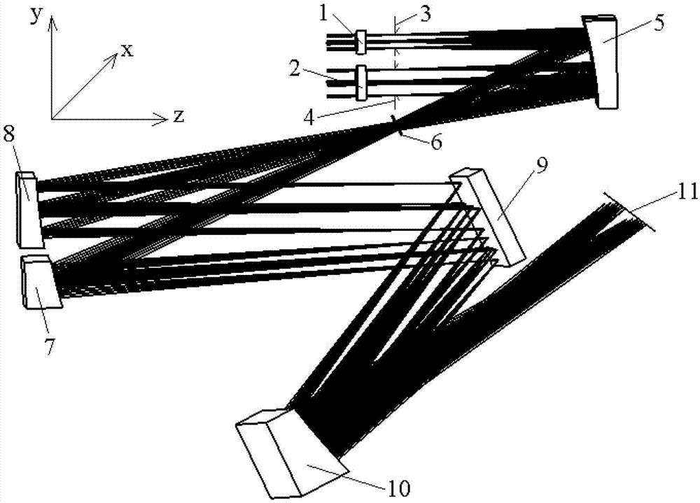
[0009] Specific implementation mode 1. Combination figure 1 Describe this embodiment, the optical system of a miniaturized broadband imaging spectrometer with two channels and a common optical path, the optical system includes a first broadband filter 1, a second broadband filter 2, a first aperture stop 3, and a second aperture stop 4. Telescope 5, incident slit 6, first collimating mirror 7, second collimating mirror 8, plane grating 9, imaging mirror 10 and detector image plane 11, the light beam that described same target exits is filtered through the first broadband The light sheet 1 and the second broadband filter 2 are divided into two channels and are respectively incident on the same telescope 5 through the first aperture stop 3 and the first aperture stop 4, and are imaged on the entrance slit 6 through the telescope 5, from the incident After the slit 6 exits, it is incident on two different regions of the same plane grating 9 after passing through the first collima...
specific Embodiment approach 2
[0013] Specific embodiment two, combine figure 1 This embodiment is described. This embodiment is the application of the dual-channel common optical path miniaturized broadband imaging spectrometer optical system described in Embodiment 1. The system described in Embodiment 1 is applied to space remote sensing atmospheric limb imaging spectrum detection. The optical system of the imaging spectrometer described in this embodiment has a focal length of 68.8 mm, a field of view of 2.4°×0.02°, and a working wavelength range of 280-1000 nm. Atmospheric limb scene is divided into two channels by the first broadband filter 1 and the second broadband filter 2 to be incident on the telescope 5. The wavelength range of the first channel is 280-540nm, and the wavelength range of the second channel is 535-535nm. 1000nm, the aperture of the first aperture stop 3 is 8.8mm, and the aperture of the second aperture stop 4 is 4.6mm, achieving the purpose of enhancing weak signals. Telescope 5 ...
PUM
 Abstract
Description
Claims
Application Information
 - R&D Engineer
- R&D Manager
- IP Professional
- Industry Leading Data Capabilities
- Powerful AI technology
- Patent DNA Extraction
Browse by: Latest US Patents, China's latest patents, Technical Efficacy Thesaurus, Application Domain, Technology Topic, Popular Technical Reports.
© 2024 PatSnap. All rights reserved.Legal|Privacy policy|Modern Slavery Act Transparency Statement|Sitemap|About US| Contact US: help@patsnap.com