Material belt shearing machine

A technology of shearing machine and strip, applied in metal processing, etc., can solve the problems of slow manual operation efficiency, hidden dangers of production safety, incomplete processing, etc., and achieve the effect of saving working time and improving the qualified rate

Inactive Publication Date: 2013-02-13
SHIN YUAN ELECTRONICS PROD KUNSHAN
View PDF9 Cites 3 Cited by
  • Summary
  • Abstract
  • Description
  • Claims
  • Application Information

AI Technical Summary

Problems solved by technology

[0002] In today's automatic processing industry, the processing technology of some products needs to cut the material tape first. During the manual operation and feeding process, it is easy to crush the worker's fingers, which brings hidden dangers to production safety. Moreover, manual operation The efficiency is very slow, which is not conducive to the rapid processing of products
In addition, in the process of full machine processing, it is easy to form substandard products due to incomplete processing.

Method used


Image

  • Material belt shearing machine

Examples


Embodiment Construction

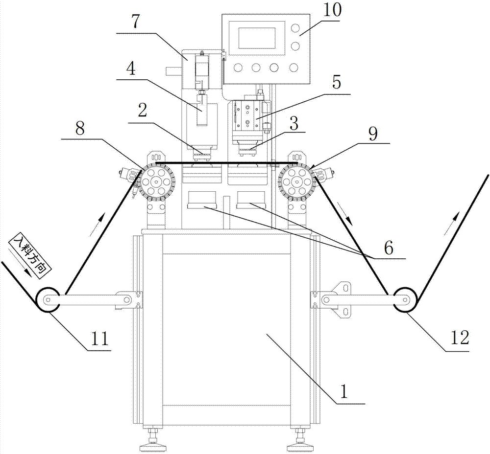
[0012] The ribbon shearing machine provided by the present invention will be further described in detail below through specific examples.

[0013] Such as figure 1 As shown, the strip shearing machine of this embodiment includes an electric control cabinet 1 , and a first die 2 and a second die 3 are installed in the middle of the upper part of the electric control cabinet 1 . The first die 2 is connected with the cam 4 above it, and the cam 4 is fixed below the stamping motor 7 . The stamping motor 7 drives the cam 4 to make the first die 2 move up and down in the vertical direction, so as to perform the first shearing process on the strip. The second die 3 is connected with the stamping cylinder 5, and the stamping cylinder 5 drives the second die 3 to move, and can perform secondary shear processing on the strip processed by the first die 2. A waste collection box 6 is installed below the first die 2 and the second die 3 for collecting waste materials cut by the first die...


PUM


Abstract

The invention discloses a material belt shearing machine which comprises an electric control cabinet, wherein the middle of the upper part of the electric control cabinet is provided with a first stamping die used for carrying out primary shearing on a material belt and a second stamping die used for carrying out secondary shearing on the material belt; and waste collecting boxes used for collecting waste materials are arranged below the first stamping die and the second stamping die, and the two sides of the top of the electric control cabinet are also respectively provided with a material inlet wheel and a feeding wheel. The material belt shearing machine provided by the invention has the advantages that the comprehensive automatic operation can be realized, the manual operation time is saved, and meanwhile, the material belt shearing qualification rate is improved through twice shearing of the first and second stamping dies.

Description

technical field [0001] The invention relates to the field of ribbon processing, in particular to a ribbon cutter. Background technique [0002] In today's automatic processing industry, the processing technology of some products needs to cut the material tape first. In the process of manual operation and feeding, it is easy to crush the workers' fingers, which brings hidden dangers to production safety. Moreover, manual operation The efficiency is very slow, which is not conducive to the rapid processing of products. In addition, in the process of full machine processing, it is easy to form substandard products due to incomplete processing. Contents of the invention [0003] The object of the present invention is: to solve the above problems, provide a strip cutter with simple structure, automatic operation, convenient work and high pass rate, so as to save working time for strip processing and improve work efficiency. [0004] The technical solution of the present inven...

Claims


Application Information

Patent Timeline
Patent Type & Authority Applications(China)
IPC IPC(8): B26F1/38B26D5/16B26D5/12
Inventor 郑吉宏王均哲
Owner SHIN YUAN ELECTRONICS PROD KUNSHAN
Why Eureka
Try Eureka