
Non-delamination drilling method based on drilling force control for carbon fiber reinforced polymer (CFRP) laminate

A technology of reinforced composite materials and drilling methods, applied in the field of mechanical processing, can solve the problems of large dependence on original data, large influence of human factors, large errors, etc., to avoid delamination damage defects, reduce production costs, and reduce product scrapping Effect

Inactive Publication Date: 2013-01-30
SHANGHAI JIAO TONG UNIV
View PDF2 Cites 12 Cited by
  • Summary
  • Abstract
  • Description
  • Claims
  • Application Information

AI Technical Summary

Problems solved by technology

This method is highly dependent on the original data, and the solution accuracy often depends on the amount of original data collected and the accuracy of the fitting function; and the delamination damage of CFRP laminates in the actual drilling process is often not easy to observe and detect, especially the The delamination damage between layers often needs to be cut open and cleaned by chemical agents to be observed. The determination of the delamination area often depends on the operator's experimental experience. Human factors are greatly affected, and the experimental operation is cumbersome and difficult. big error
[0004] After searching the existing literature, no public reports on the delamination-free drilling method for carbon fiber reinforced composite laminates have been found so far

Method used


Image

  • Non-delamination drilling method based on drilling force control for carbon fiber reinforced polymer (CFRP) laminate
  • Non-delamination drilling method based on drilling force control for carbon fiber reinforced polymer (CFRP) laminate
  • Non-delamination drilling method based on drilling force control for carbon fiber reinforced polymer (CFRP) laminate

Examples


Embodiment

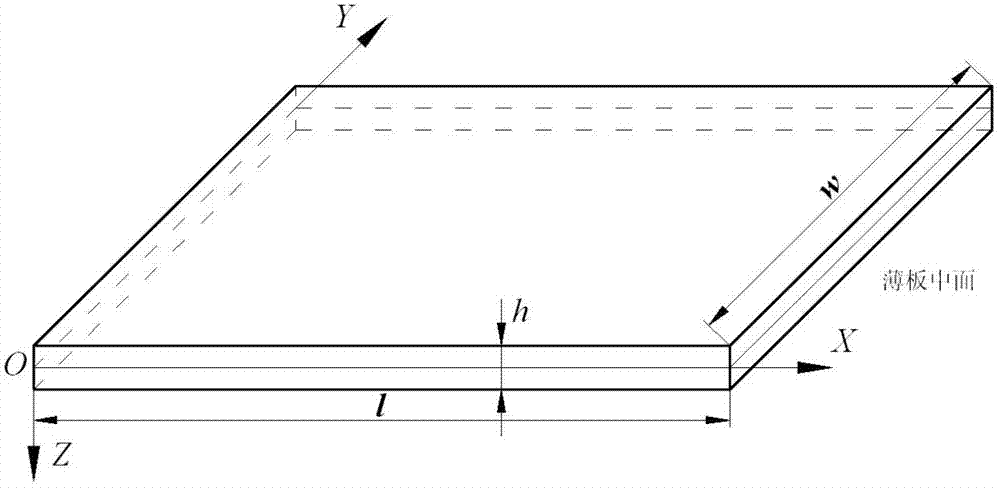
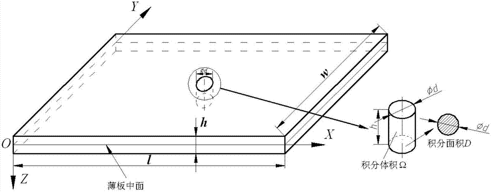
[0050] In this example, a cemented carbide twist drill with a diameter of 4.9 mm is used to drill and process T300 / 250F CFRP laminates. The determination of the critical thrust of the drilling layer includes the following steps, please refer to figure 1 , figure 2 with image 3 :

[0051] In the first step, when the drill bit is drilling the CFRP laminate, at the moment when the material is about to delaminate, the drilling axial force does work along the deflection direction of the CFRP laminate, and part of it is used to overcome the bending deformation of the CFRP laminate and convert it into The other part of the bending potential energy inside the matrix is ​​converted into the surface energy required for the propagation of delamination cracks in the plate. When the strain energy (the difference between the work done by the drilling axial force along the deflection direction of the CFRP laminate and the bending potential energy of the CFRP laminate) is exactly equal to...


PUM


Abstract

The invention discloses a non-delamination drilling method based on drilling force control for a carbon fiber reinforced polymer (CFRP) laminate. In the method, in a process of drilling a carbon fiber reinforced polymer (CFRP) laminate with a drill bit, the drilling axial force of the drill bit is controlled to be always smaller than a drilling delamination critical thrust value Fa, wherein Fa is determined by the following steps of: establishing a delamination stable state equation of the CFRP laminate; establishing a polar equation of a small-deflection sheet and a CFRP laminate defection formula of the drill bit during drilling to evaluate the maximum deflection value X of the CFRP laminate; establishing a bending deformation energy formula of the CFRP laminate during drilling, and evaluating the bending deformation energy U of the CFRP laminate during drilling of the drill bit; and determining a drilling delamination critical thrust value Fa according to the evaluated maximum deflection X, the bending deformation energy U and the established delamination stable state equation of the CFRP laminate. Due to the adoption of the method, non-delamination drilling processing of the CFRP laminate is realized, the delamination damage defect of drilling is avoided, the product quality is improved, the cost is lowered, and the efficiency is increased.

Description

technical field [0001] The invention relates to a drilling method, in particular to a non-layered drilling method for a carbon fiber reinforced composite laminate based on drilling force control, and belongs to the technical field of mechanical processing. Background technique [0002] Carbon Fiber Reinforced Polymer (CFRP) is a new type of resin-based composite material reinforced with carbon or graphite fibers, because of its high strength, high specific stiffness, good fatigue resistance and designability Strong and other advantages are widely used in the manufacture of main load-bearing structural parts on advanced aircraft, such as aircraft skin, wall panels, wing middle beams, fuselage bulkheads and hatches. In the cutting process of CFRP, drilling is the most widely used and widely used material processing method, and it is also the final link in the assembly of aerospace structural parts. The quality of drilling holes is directly related to the assembly quality and ...

Claims


Application Information

Patent Timeline
IPC IPC(8): B26F1/16
Inventor 安庆龙徐锦泱蔡晓江魏莹莹陈明
Owner SHANGHAI JIAO TONG UNIV
Learn More