
Remote control receiving control method without alternating-current standby power consumption and remote control receiving circuit without alternating-current standby power consumption

A technology of remote control reception and standby power consumption, applied in non-electrical signal transmission systems, signal transmission systems, instruments, etc., can solve the problems of one-way communication, no feedback, slow communication speed, etc., achieve wide application space, and compact circuit structure , The effect of saving standby power consumption

Active Publication Date: 2013-01-23
刘硕
View PDF5 Cites 8 Cited by
  • Summary
  • Abstract
  • Description
  • Claims
  • Application Information

AI Technical Summary

Problems solved by technology

[0006] With the continuous advancement of technology, the directional infrared remote control solution is inconvenient to use, slow communication speed, small amount of information, one-way communication, no feedback, and no obstacles between the remote control and the receiving circuit. The shortcomings will be gradually eliminated, and the non-directional technology that overcomes the above shortcomings will have a broader development space

Method used


Image

  • Remote control receiving control method without alternating-current standby power consumption and remote control receiving circuit without alternating-current standby power consumption
  • Remote control receiving control method without alternating-current standby power consumption and remote control receiving circuit without alternating-current standby power consumption
  • Remote control receiving control method without alternating-current standby power consumption and remote control receiving circuit without alternating-current standby power consumption

Examples


Embodiment 1

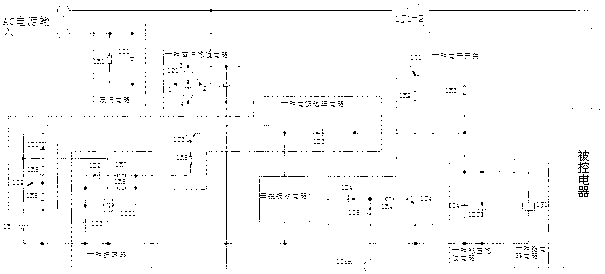
[0060] Such as image 3 As shown, in this embodiment, the micro-power oscillator circuit includes a digital logic circuit: a Schmitt trigger 1IC1, a diode 1D2, resistors 1R7, 1R8, and a capacitor 1C3, wherein, after the diode 1D2 is connected in series with the resistor 1R7, The two are connected in parallel with the resistor 1R8, and are connected between the input terminal 1 and the output terminal 4 of the Schmitt trigger 1IC1 at the same time. The input terminal 1 of the Schmitt trigger 1IC1 is grounded through the capacitor 1C3, and the Schmitt trigger 1IC1 Terminal 2 is the power supply terminal, and terminal 3 is the common terminal grounding;

[0061] The power gating circuit includes PNP transistor 1T2 and NPN transistor 1T3, diodes 1D1 and 1D3, resistors 1R5 and 1R6, wherein the negative pole of the power supply battery 1E is connected to the common terminal, its positive pole is connected with the emitter of the triode 1T2, and the The collector is connected to the...

Embodiment 2

[0069] Such as Figure 4 As shown, in this embodiment, the micro-power oscillator circuit adopts a digital logic circuit: a bistable multivibrator circuit structure composed of gate circuits 2IC1 and 2IC2, including NOT gates 2IC1 and 2IC2, and a diode 2D2, a resistor 2R6 and 2R7, capacitor 2C2, wherein, terminal 5 of 2IC1 is used as the power supply terminal of the oscillator, output terminal 4 of 2IC2 is used as the output terminal of the oscillator, output terminal 2 of 2IC1 is connected with input terminal 3 of 2IC2, and the cathode of diode 2D2 Connect to the output terminal 2 of 2IC1, connect the positive pole to the input terminal 1 of 2IC1 after being connected in series with the resistor 2R6, the resistor 2R7 is connected in parallel between the input terminal 1 and the output terminal 2 of 2IC1, and one end of the capacitor 2C2 is connected across the NOT gate Between the input terminal 1 of 2IC 1 and the output terminal 4 of the NAND gate 2IC2, terminal 6 of 2IC1 is...

Embodiment 3

[0077] Such as Figure 5As shown, in this embodiment, the micro-power oscillator circuit adopts a digital logic circuit: 7555 time base circuit chip 3IC1, and also includes a peripheral circuit composed of diode 3D3, resistors 3R4, 3R5, 3R6 and capacitor 3C2. The discharge end of the 7555 time base circuit chip 3IC1 is connected to the common terminal of the system through the series connected resistor 3R6 and capacitor 3C2, and the diode 3D3 and the resistor 3R4 are connected in parallel on the resistor 3R6 after being connected in series. Both the trigger terminal and the trigger terminal are connected to the common contact between the resistor 3R4 and the resistor 3R6. After the reset terminal of the 7555 time base circuit chip 3IC1 is connected to the power supply terminal, as the power supply terminal of the oscillator, it is connected with the cathode of the diode 3D6 in the power supply gating circuit, and the resistor 3R5 is connected between the power supply terminal ...


PUM


Abstract

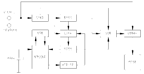
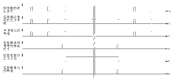
The invention discloses a remote control receiving control method without alternating-current standby power consumption. The method comprises the following steps that: power is supplied to a micro-power oscillator by batteries; periodic pulses are generated by the oscillator; periodic short-term power is supplied to a remote control receiving circuit by a power gating circuit; received signals are recognized by the remote control receiving circuit when power is supplied to the remote control receiving circuit; if the received signals are invalid, processing is not performed; if the received signals are valid, a level is output to conduct an electronic switch and a stable direct-current power supply is obtained; in the first aspect, the stable direct-current power is provided for the absorption of a relay; the power supply of a controlled electrical appliance is switched on by a relay contact so that the controlled electrical appliance works; in the second aspect, the batteries are replaced by the power gating circuit, and the power is supplied to the remote control receiving circuit; when a shutdown signal transmitted from a remote controller is received by the receiving circuit, and after the shutdown signal is recognized successfully, and the electronic switch is switched off; at the moment, a voltage-stabilization filter circuit losses power, the relay releases, the relay contact is switched off, and the controlled electrical appliance stops working; and in the third aspect, a battery power supply circuit is switched on by the power gating circuit, and the initial waiting state is recovered. Simultaneously, the invention also discloses a remote control receiving circuit without the alternating-current standby power consumption.

Description

technical field [0001] The invention relates to the technical field of electrical remote control, and also to the technical field of energy saving, in particular to a remote control receiving control method without AC standby power consumption, and also relates to a remote control receiving control circuit without AC standby power consumption. Background technique [0002] Almost all electric appliances with remote control now either turn off with the remote control, or operate the light touch key of the electric appliance to turn off, or turn off the mechanical power switch manually. After the remote control is used to turn off the power and the light touch button is used to turn off the power, the electrical appliances have standby power consumption. According to statistics, this kind of standby power consumes as much as tens of billions of electrical energy per year. If you manually turn off the mechanical power switch, it is inconvenient, and the mechanical switch is eas...

Claims


Application Information

Patent Timeline
IPC IPC(8): G08C17/02G08C23/04
Inventor 刘硕刘忠宪
Owner 刘硕
Learn More