
Combined-type SVPWM method

A modulation method and combined technology, applied in control systems, control generators, vector control systems, etc., can solve the problems of large inverter generation, large inverter losses, and low efficiency of motor drive systems.

Active Publication Date: 2013-01-16
UNITED AUTOMOTIVE ELECTRONICS SYST
View PDF6 Cites 17 Cited by
  • Summary
  • Abstract
  • Description
  • Claims
  • Application Information

AI Technical Summary

Problems solved by technology

[0021] First, large inverter losses will make the motor drive system inefficient, which will affect the range of electric vehicles
[0022] Second, the high loss of the inverter will also generate relatively high heat, resulting in excessive heat dissipation load of the cooling system of new energy vehicles
Considering that the actual cooling capacity of the inverter is limited, in order to prevent the inverter from generating a lot of heat, it is necessary to limit the current flowing through the inverter so that it cannot be too large, thus limiting the current output capability of the inverter

Method used


Image

  • Combined-type SVPWM method
  • Combined-type SVPWM method
  • Combined-type SVPWM method

Examples


Embodiment Construction

[0046] According to the different modulation principles of seven-segment SVPWM, flat-top SVPWM, half-frequency SVPWM, and FFC SVPWM, in the simulation software (such as Matlab software equipped with Simulink toolkit, etc.), the four SVPWM methods are tested in each permanent magnet synchronous motor. The electromagnetic torque fluctuation at the operating point (at different speeds and different torques) is compared with the loss of power switching devices (such as diodes, IGBT devices, etc.), and the simulation results are shown in the following four tables.

[0047]

[0048]

[0049] Table 2 Original simulation results under small torque

[0050]

[0051]

[0052] Table 3 Original simulation results under medium torque

[0053]

[0054] Table 4 Original simulation results under high torque

[0055]

[0056]

[0057] Table 5 The original simulation results of seven-segment and FFC

[0058] see Figure 11 to Figure 13 , are the actual electromagnetic to...


PUM


Abstract

The invention discloses a combined-type SVPWM (Space Vector Pulse Width Modulation) method. Different SVPWM methods are adopted according to different stator frequencies of an AC motor; when the stator frequency of the AC motor is lower than the low-frequency sector, a half-frequency method is adopted; when the stator frequency of the AC motor is in the medium-and-low frequency sector, a flat-top SVPWM method is adopted; when the stator frequency of the AC motor is in the medium-and-high frequency sector, a seven-segment SVPWM method is adopted; and when the stator frequency of the AC motor is in the high-frequency sector, an FFC (Fundamental Frequency Clocking) SVPWM method. Usually, for power loss of an inverter, the seven-segment SVPWM method is larger than the flat-top SVPWM method, the flat-top SVPWM method is larger than the half-frequency SVPPWM method, and the half-frequency SVPPWM method is larger than the FFC SVPWM method; and for the torque control precision, the four methods are optimal within different frequency ranges. According to the invention, the four SVPWM method are used together, different SVPWM methods are adopted according to different working conditions of the motor so as to play respective potentials; and therefore, lower power loss of the inverter and higher torque control precision are drawn into consideration, and the output power of the motor running in the high-frequency sector is increased.

Description

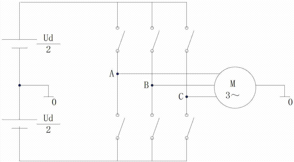
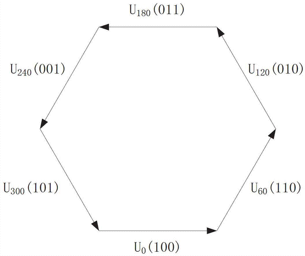
technical field [0001] The present application relates to a control method of an AC motor, in particular to a SVPWM (space vector PWM, voltage space vector pulse width modulation) method. Background technique [0002] SVPWM is a control method for AC motors. This method considers the inverter and the AC motor as a whole, and no longer sticks to making the output voltage of the inverter as close as possible to the three-phase symmetrical sine wave, but focuses on making the AC The motor tries to form a circular flux linkage trajectory, and uses this as a goal to control the switching state of the inverter to form a PWM waveform. [0003] Commonly used SVPWM methods include seven-segment SVPWM, Flat-Top SVPWM, half-frequency SVPWM, FFC (Fundamental Frequency Clocking) SVPWM, and the like. [0004] see figure 1 , which is a schematic diagram of a three-phase inverter powering an AC motor. The three-phase inverter has three bridge arms A, B, and C, and each bridge arm is comp...

Claims


Application Information

Patent Timeline
Patent Type & Authority Applications(China)
IPC IPC(8): H02P21/14H02P27/08
Inventor 马艳丽张东海颜宇杰
Owner UNITED AUTOMOTIVE ELECTRONICS SYST
Learn More