
Low humidity steam flash double effect heat exchange system

A technology of heat exchange system and low humidity, which is applied in the field of low humidity steam flash two-effect heat exchange system, which can solve the problems of decreased drainage capacity, affecting normal production, low heat exchange efficiency and energy efficiency, etc.

Inactive Publication Date: 2014-04-23
YIHENG ENERGY SAVING TECH JIANGSU
View PDF5 Cites 0 Cited by
  • Summary
  • Abstract
  • Description
  • Claims
  • Application Information

AI Technical Summary

Problems solved by technology

The shortcomings of the existing water-bath saturated steam generators are: the water content in the saturated steam is high, and the steam quality is poor
After the high-temperature condensed water enters the condensed water pipe, the pressure drops continuously along the way, part of the high-temperature condensed water flashes into steam, the volume expands by more than 1000 times, and the flow rate increases by about 10 times, which is very easy to form steam resistance; after the steam resistance, the back pressure of the trap increases , the pressure difference between the two ends of the trap decreases, and the drainage capacity decreases, resulting in the condensed water generated in the heat exchanger cannot be removed in time, the efficiency of the heat exchanger decreases, and the material temperature cannot meet the process requirements, thus affecting normal production
In order to ensure production, it is often necessary to open the shut-off valve in parallel with the steam trap for direct discharge. The steam pressure leaked from the shut-off valve offsets the steam resistance; although the production is guaranteed, the steam utilization rate is reduced and the steam consumption per unit product is increased.
Therefore, the heat exchange efficiency and energy efficiency of the existing heat exchange system are relatively low.

Method used


Image

  • Low humidity steam flash double effect heat exchange system

Examples


Embodiment Construction

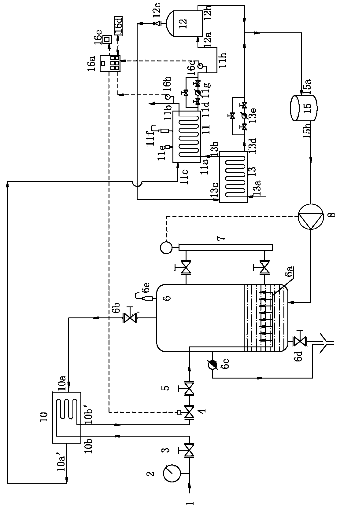
[0016] Such as figure 1 As shown, the low-humidity steam flash two-effect heat exchange system of the present invention includes a superheated steam pipe, a water bath type saturated steam generator 6, a make-up water pump 8, a steam drying heat exchanger 10, a main steam heat exchanger 11, a flash evaporation tank 12, flash steam heat exchanger 13, water collection tank 15 and PLC controller 16a.

[0017]The lower part of the cylinder of the water-bath saturated steam generator 6 is a liquid phase space, and the upper part of the cylinder is a vapor phase space. The top wall of the vapor phase space is provided with a water-bath saturated steam generator exhaust valve 6b, and the water-bath saturated steam generator A flow divider 6a is provided in the liquid phase space of 6 . A water level gauge 7 and an overflow valve 6c are installed on the side wall of the water bath type saturated steam generator 6, and the overflow valve 6c can be a ball float type steam trap. The ou...


PUM


Abstract

The invention relates to a low humidity steam flash double effect heat exchange system. A liquid phase space in a water bath saturated steam generator is provided with a flow diverter, a steam drying heat exchanger is arranged on a steam discharge pipe of the flow diverter. Superheated steam enters into the flow diverter through a pressure control valve. Wet saturated steam from the saturated steam generator is heated by the superheated steam as dry saturated steam which enters into main steam heat exchanger to re-heat materials and form as high temperature condensed water. Flash steam after flash of the high temperature condensed water heats materials in the flash steam heat exchanger, and the flash steam condensed water enters into a water collecting tank and is pumped into the saturated steam generator by a water supplementing pump. A PLC (Programmable Logic Controller) adjusts the openness of the pressure control valve according to the temperature of a material outlet. The system utilizes cascaded steam heat energy and ensures that the steam heat energy is exhausted, so that the energy efficiency is improved.

Description

technical field [0001] The invention relates to a steam heat exchange system, in particular to a low-humidity steam flash evaporation double-effect heat exchange system. Background technique [0002] In indirect heat exchange, the heat exchange efficiency of saturated steam is higher than that of superheated steam, and the higher the degree of superheat, the lower the heat exchange efficiency. When there is only superheated steam source, it is necessary to reduce the temperature of the superheated steam to reduce the degree of superheat. Generally, steam desuperheaters such as spray desuperheater, surface desuperheater, etc. are used. The lower the superheat after desuperheating, the more serious the steam will be with water, and the worse the steam quality will be. If it is necessary to reduce the steam temperature to the saturation temperature corresponding to the required steam pressure, a water-bath saturated steam generator is usually used, also known as a water-bath s...

Claims


Application Information

Patent Timeline
Patent Type & Authority Patents(China)
IPC IPC(8): F22G5/12
Inventor 杨晓辉张基虎杨思伦张梦颖
Owner YIHENG ENERGY SAVING TECH JIANGSU
Learn More