
Light-emitting diode (LED) light-distributing lens

A light distribution lens and lens technology, applied in the direction of light source, fixed light source, point light source, etc., can solve the problems of inability to meet the requirements of high-end lighting occasions, limited ability to homogenize and modulate the light field, uneven color of the lighting area, etc. Flexible control of angle and area distribution, overcoming the phenomenon of uneven color distribution, overcoming the effect of uneven color

Inactive Publication Date: 2013-01-16
成都欧盛光电科技有限公司
View PDF0 Cites 22 Cited by
  • Summary
  • Abstract
  • Description
  • Claims
  • Application Information

AI Technical Summary

Problems solved by technology

These defects are acceptable in some low-demand large-angle flood lighting applications, but often cannot meet the requirements in high-end lighting applications
Especially in small-angle fixed-point lighting, it is easy to produce uneven color in the lighting area
In order to overcome this phenomenon, the traditional light distribution lens usually sets a lens array with consistent surface parameters on the exit surface of the light distribution lens or makes the exit surface of the lens a matte surface. The disadvantages are: the first is homogenization modulation The ability of the light field is limited, and the second is to affect the light output efficiency of the lens

Method used


Image

  • Light-emitting diode (LED) light-distributing lens
  • Light-emitting diode (LED) light-distributing lens
  • Light-emitting diode (LED) light-distributing lens

Examples


Embodiment 1

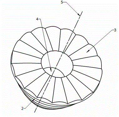
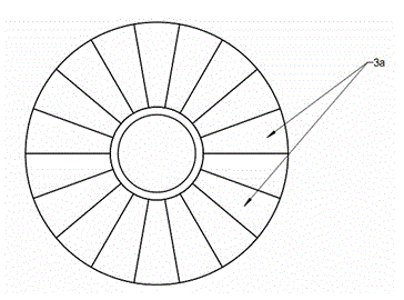
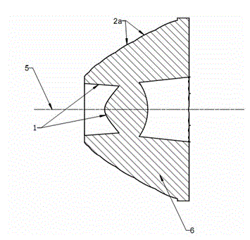
[0045] Such as Figure 1 to Figure 3 As shown, the LED light distribution lens of the present invention includes a lens body 6. The shape of the lens body 6 is approximately conical. The bottom is concave, and the LED light source can be installed in the concave space area. The incident surface 1 is used to receive the light of the LED light source close to this side, and the light of the LED light source is refracted by the incident surface 1 to form incident light inside the lens body 6; The reflection surface 2 is arranged on the side of the lens body 6, and is used for redirecting and reflecting the light inside the lens body 6 to the exit surface. After the light is refracted, it is emitted and projected to the illuminated area. The reflective surface 2 is sequentially spliced ​​by several annular surfaces 2a arranged along the axial direction of the lens body 6. The diameters of the several annular surfaces 2a are gradually increased from the incident surface 1 to the ex...

Embodiment 2

[0050] The difference between this embodiment and Embodiment 1 is that the generatrix of the annular surface 2a is a curve. By changing the curvature of the generatrix on the annular surface 2a, the reflected light can be accurately irradiated in the illumination area as required, which is more conducive to the light in the illumination area. Flexible adjustment within.

[0051] Please refer to Embodiment 1 for other structures.

Embodiment 3

[0053] The difference between this embodiment and Embodiment 1 lies in that the generatrix of the annular surface 2a is a straight line, and in this way, the light extraction efficiency is high, and the processing and manufacturing are convenient.

[0054] Please refer to Embodiment 1 for other structures.


PUM


Abstract

The invention relates to a light-emitting diode (LED) light-distributing lens. The LED light-distributing lens comprises a lens body, wherein the lens body is defined by an incident plane, a reflecting plane and an emergent plane together; the incident plane is concave inwards at the bottom of the lends body; the reflecting plane is arranged on a side face of the lens body and is formed by assembling a plurality of annular surfaces together in sequence, which are axially arranged along the lens body; the curvature of the assembled part of two adjacent annular surfaces is discontinuous; the annular planes are arranged to form an annular step-shaped reflecting plane; and different annular surfaces receive incident light rays which correspond to the annular surfaces respectively and have different included angle ranges with the axis of the lens body, and then reflect the incident light rays, so that large-angle light rays which are emitted by a light source are subjected to differential segmentation according to the different included angles between the large-angle light rays and the axis of the lens body.

Description

technical field [0001] The invention relates to an LED light distribution lens, in particular to an LED light distribution lens through differential and integral processing of light. Background technique [0002] As a new energy-saving light source, LED has been widely used in various lighting occasions, such as spotlights, street lights, working lights, etc. They replace traditional light sources and greatly improve the electro-optic conversion efficiency. However, with the development of LED chip technology and the development of application requirements, the LED light source is often no longer a continuous uniform light-emitting surface or light-emitting body. For example, in order to further improve the light extraction efficiency of the LED light source, some LED light source manufacturers carve grooves on the chip, and the grooves carved will cause inconsistent light emission on the chip. For another example, in order to meet high-power lighting, many packaging ma...

Claims


Application Information

Patent Timeline
Patent Type & Authority Applications(China)
IPC IPC(8): F21V5/04F21V17/00F21Y101/02
Inventor 霍永峰
Owner 成都欧盛光电科技有限公司
Learn More