
Pneumatic ball valve reliable in sealing and low in opening-closing torque

A pneumatic ball valve, reliable technology, used in valve devices, engine components, cocks including cut-off devices, etc., can solve problems such as easy damage, troublesome ball valve design, damage to valve sealing surfaces, etc.

Active Publication Date: 2013-01-16
CHAODA VALVE GRP
View PDF10 Cites 14 Cited by
  • Summary
  • Abstract
  • Description
  • Claims
  • Application Information

AI Technical Summary

Problems solved by technology

However, the greater the force of the medium acting on the back of the valve seat, the greater the bonding force between the ball and the sealing ring of the valve seat, and the greater the friction between them, the greater the operating force is required to open the valve, or more large drive mechanism
In addition, when the sealing force between the ball and the sealing ring of the valve seat is too large, it is easy to cause damage to the sealing surface of the valve when the valve is opened, especially when the medium contains solid particles, it is more likely to be damaged
In short, from the perspective of improving the sealing performance of the valve seat, it is necessary to increase the thrust of the medium behind the valve seat, but from the perspective of reducing the opening and closing torque of the valve and preventing damage to the sealing surface, it is necessary to reduce the thrust of the medium behind the valve seat, Therefore, this is a contradiction that has plagued the design of ball valves for a long time.

Method used


Image

  • Pneumatic ball valve reliable in sealing and low in opening-closing torque
  • Pneumatic ball valve reliable in sealing and low in opening-closing torque
  • Pneumatic ball valve reliable in sealing and low in opening-closing torque

Examples


Embodiment Construction

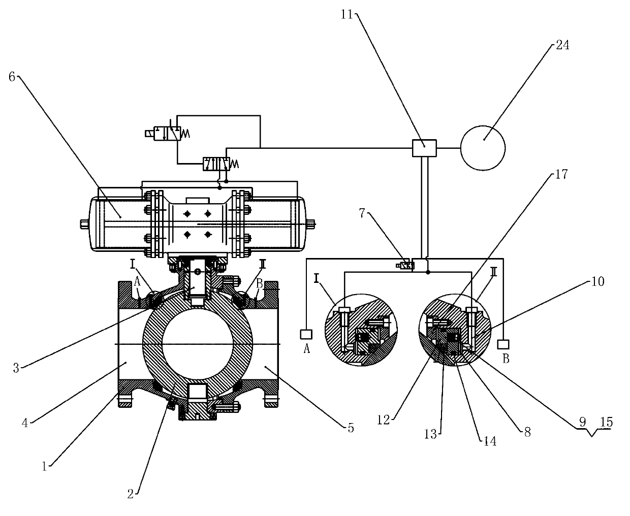
[0016] Such as image 3 As shown, the pneumatic ball valve with reliable sealing and small opening and closing torque includes a ball valve body 1 with a valve cavity, a ball 2 placed inside the valve cavity, a valve stem 3 linked to the ball 2 and a ball valve body 1 and the ball 2. The two sides of the valve cavity are connected with the inlet channel 4 and the outlet channel 5 respectively, and the valve stem 3 is partially exposed outside the ball valve body 1, and the ball valve body 1 is equipped with a pneumatic device to drive the valve stem 3 to rotate 6. The valve seat sealing mechanism includes an annular valve seat assembly and a three-way reversing valve 7. The inner wall of the ball valve body 1 is provided with an annular valve seat assembly chamber 8 with an opening facing the ball 2. The valve seat assembly Relative to the ball 2, it is slidably arranged in the annular valve seat assembly cavity 8, and the valve seat assembly and the annular valve seat assembl...


PUM


Abstract

The invention relates to a valve, in particular to a pneumatic ball valve reliable in sealing and low in opening-closing torque. The pneumatic ball valve comprises a ball valve body with a valve cavity, a ball positioned in the valve cavity, a valve rod in linkage with the ball and a valve seat sealing mechanism arranged between the ball valve body and the ball. A valve seat component and an annular valve seat component cavity are in airtight fit to form a structure similar to a piston. A pre-tensioning elastic part and a three-way reversing valve are arranged on one side, opposite to the ball, of the ball valve body. The three-way reversing valve and a pressure control reversing valve are used for controlling pressure applied to the ball by the valve seat component under different conditions and an operating air source of a pneumatic device to realize the fact that when the valve is closed, the pressure applied to the ball by the valve seat component is large, the sealing performance is fine, and when the valve is opened, the pressure applied to the ball by the valve seat component is small. Therefore, the opening power is low, a ball sealing face and a valve seat sealing face are less prone to damage during opening, the service life of the ball valve is prolonged, and the pneumatic ball valve has a function of preventing misopertion of opening when large pressure is applied to the ball by the valve seat.

Description

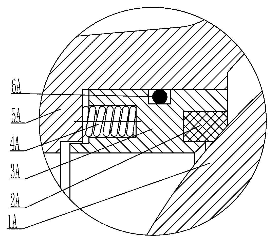
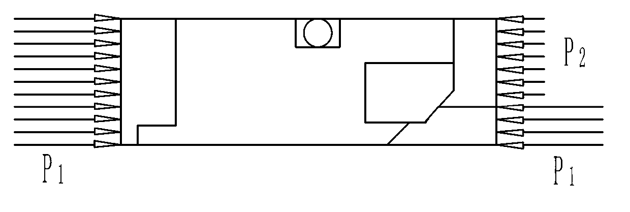
technical field [0001] The invention relates to a valve, in particular to a pneumatic ball valve with reliable sealing and small opening and closing torque. Background technique [0002] Pneumatic ball valve is a kind of valve that is widely used. Its structure usually includes a ball valve body with a valve cavity, a ball placed inside the valve cavity, a valve stem linked to the ball, and a valve seat placed between the ball valve body and the ball. The valve stem part is exposed outside the ball valve body, and the outside of the ball valve body is equipped with a pneumatic device that drives the valve stem to rotate. Toggle off. Seat sealing structure and force analysis of traditional trunnion ball valve figure 1 , 2 As shown in the figure, 1A is the sphere, 2A is the valve seat sealing ring, 3A is the valve seat, 4A is the spring, 5A is the ball valve body, 6A is the seal between the ball valve body and the valve seat, and the seal between the ball and the valve seat...

Claims


Application Information

Patent Timeline
IPC IPC(8): F16K5/06F16K5/20
Inventor 邱晓来王汉洲黄明金林洁
Owner CHAODA VALVE GRP
Learn More