Self-cleaning oil recharging lockup valve of combination type hydraulic cylinder

A locking valve and self-cleaning technology, applied in servo motor components, fluid pressure actuation devices, fluid pressure actuation system components, etc., can solve problems such as component cavitation, hydraulic pump and motor wear, cavitation, etc., to achieve Strong anti-pollution ability, convenient installation and maintenance, and achieve the effect of single cycle

Inactive Publication Date: 2013-01-16
ZHENGZHOU YUTONG HEAVY IND
View PDF5 Cites 1 Cited by
  • Summary
  • Abstract
  • Description
  • Claims
  • Application Information

AI Technical Summary

Problems solved by technology

[0002] With the development of large-scale and high-power construction machinery and mining machinery, the application of hydraulic transmission is becoming more and more extensive. The air inside the hydraulic circuit and hydraulic cylinder is difficult to get rid of, resulting in failures such as telescopic crawling of the hydraulic cylinder and component cavitation
Especially for newly assembled products or products after a long shutdown, the air generated by the pipeline will stay in the hydraulic circuit for a long time, causing system failure
[0003] In many occasions, hydraulic cylinders work under heavy load and high-speed conditions. Due to insufficient flow supply of the system, problems such as negative pressure and air suction in one cavity of the hydraulic cylinder occur, resulting in dangers such as crawling and cavitation.
[0004] In addition, some construction machinery and mining machinery work in harsh environments, and small particles such as dust will adhere to the piston rod. With the expansion and contraction of the piston rod, they will enter the interior of the hydraulic cylinder and the hydraulic circuit, causing the hydraulic valve to be stuck, and accelerate the hydraulic pump and Problems or failures such as motor wear

Method used


Image

  • Self-cleaning oil recharging lockup valve of combination type hydraulic cylinder
  • Self-cleaning oil recharging lockup valve of combination type hydraulic cylinder
  • Self-cleaning oil recharging lockup valve of combination type hydraulic cylinder

Examples


Embodiment Construction

[0025] The present invention will be further described in detail below with reference to the embodiments (accompanying drawings).

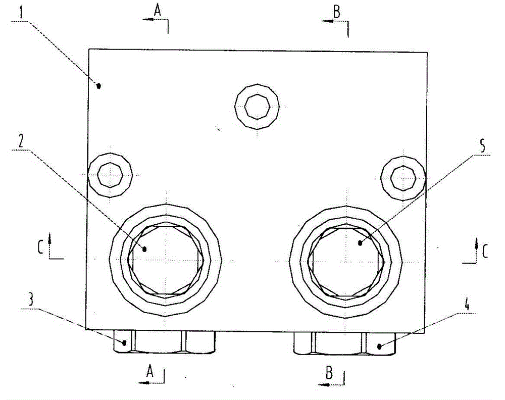
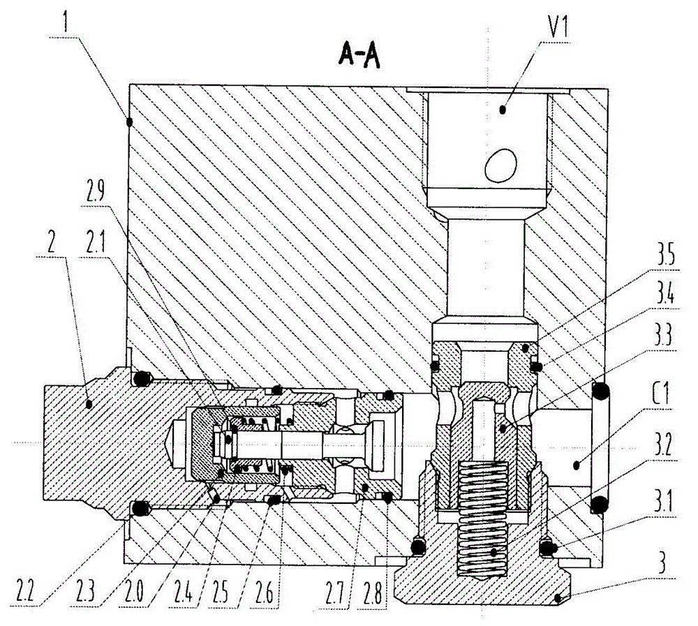
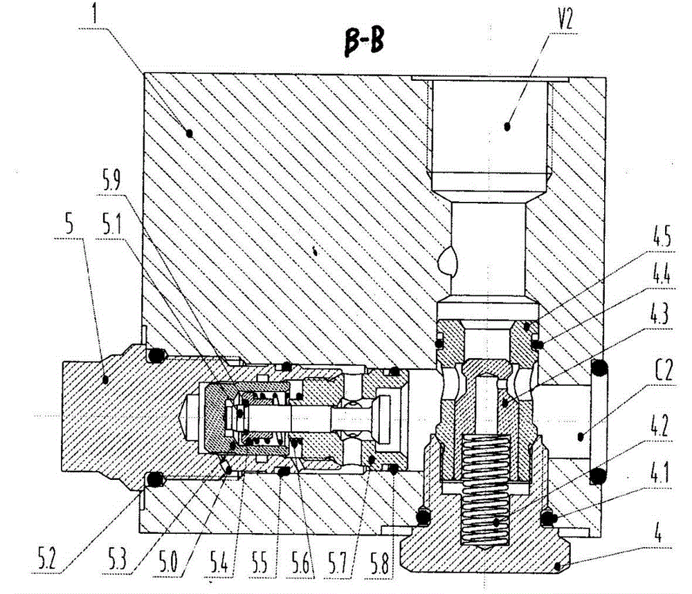
[0026] Such as Figures 1 to 5 As shown, the combined oil pressure cylinder self-cleaning oil supply lock valve of the present invention includes a valve body 1 provided with an oil inlet V1, an oil outlet C1, an oil inlet V2 and an oil outlet C2, and the first valve body 1 arranged in the valve body One and two one-way valve assemblies 3, 4 and the first and second hydraulic control one-way valve assemblies 2, 5; the oil inlet V1 of the valve body is connected to the axial port of the first one-way valve assembly valve body 3.5 and the valve body The working oil port C1 of the valve body communicates with the 3.5 radial oil port of the first check valve assembly valve body and the 2.7 axial oil port of the first hydraulic control check valve assembly valve body, and the oil inlet port of the valve body V2 communicates with the 4.5 axial port of ...


PUM


Abstract

A self-cleaning oil recharging lockup valve of a combination type hydraulic cylinder is characterized by comprising a valve body with an oil inlet V1, an oil outlet C1, an oil inlet V2 and an oil outlet C2, and a first check valve component, a second check valve component, a first hydraulic control check valve and a second hydraulic control check valve which are arranged in the valve body; and the oil inlet V1 of the valve body is communicated with an axial port in a valve body of the first check valve component and an oil passage in the valve body, the working oil outlet C1 in the valve body is communicated with a radial oil port in the valve body of the first check valve component and an axial oil port in the valve body of the first hydraulic control check valve, the oil inlet V2 of the valve body is communicated with the axial port in the valve body of the second check valve component and the oil passage in the valve body, the working oil outlet C2 in the valve body is communicated with the radial oil port in the valve body of the first check valve component and the radial oil port in the valve body of the first hydraulic control check valve, the oil passage in the valve body is communicated with a hydraulic port of the second hydraulic control check valve, the oil passage in the valve body is communicated with the hydraulic port of the first hydraulic control check valve, and an oil return port T in the valve body is communicated with the radial oil port in the valve body of the first hydraulic control check valve and the radial oil port in the valve body of the second hydraulic control check valve.

Description

technical field [0001] The invention relates to the technical fields of construction machinery and hydraulic control, in particular to a self-cleaning and oil-supplement locking valve of a combined oil pressure cylinder with the functions of self-discharging, exhausting and oil-supplementing. Background technique [0002] With the development of large-scale and high-power construction machinery and mining machinery, the application of hydraulic transmission is becoming more and more extensive. The air inside the hydraulic circuit and hydraulic cylinder is difficult to get rid of, resulting in failures such as telescopic crawling of the hydraulic cylinder and component cavitation. Especially for newly assembled products or products that have been shut down for a long time, the air generated by the pipeline will stay in the hydraulic circuit for a long time, causing system failure. [0003] In many occasions, there are hydraulic cylinders working under heavy load and high-spe...

Claims


Application Information

Patent Timeline
Patent Type & Authority Applications(China)
IPC IPC(8): F15B13/04F15B21/04
Inventor 杨虎堵利宾王昉郑磊李楠张四全
Owner ZHENGZHOU YUTONG HEAVY IND
Why Eureka
Try Eureka