
Twisting and spooling combine

An all-in-one machine and tube-forming technology, which is applied to spinning machines, continuous winding spinning machines, textiles and papermaking, etc., can solve the problems of insufficient support, easy deformation, and low strength of paper tubes, so as to prevent falling off or Radial rotation, prevent loosening up and down, good locking effect

Active Publication Date: 2013-01-16
GAOXIAN CHANGXIN LINE
View PDF9 Cites 0 Cited by
  • Summary
  • Abstract
  • Description
  • Claims
  • Application Information

AI Technical Summary

Problems solved by technology

[0008] 1. The cost of the plastic bobbin used now is high
[0009] 2. Since the traditional process is to wind the thread on the plastic bobbin in a spindle shape, it is easy to deform during transportation, resulting in a large amount of waste products; and the weight of the winding thread is light and the length of the winding thread is relatively short. For customers who need long threads, It is also necessary to increase the winding process to meet the user's requirements, which is inconvenient to use; the motor load does not meet the power requirements of winding long wires, and the operation and control methods are inconvenient
[0010] 3. If you choose an environmentally friendly and low-cost paper tube, due to the low strength of the paper tube, the bottom end is likely to cause product pollution when winding the wire, or even fail to produce, so a base structure is needed to fix the paper tube
[0012] But this patent still does not solve the following technical problems: the thread is wound on the loose bobbin in a spindle shape, the supporting force of the rotating shaft for the loose bobbin is not enough, and the fixing of the rotating shaft and the loose bobbin is not firm, so that the loose bobbin It will slide relative to the rotating shaft, and the loose bobbin is easy to deform, and it is inconvenient to exchange it from the rotating shaft after deformation; if the loose bobbin is sold directly, the cost of purchasing the loose bobbin is high, and it is easy to deform during transportation, resulting in waste products The rate is high; and it is not suitable to use paper tubes as loose bobbins
[0014] This patent also has the following deficiencies in actual use: 1. The manufacturing process of the anti-jamming shaft bobbin device is complicated, and the price is high, resulting in increased production costs; 2. The spindle bar cannot use paper tubes to wind yarns. The fixation is not firm and the supporting strength is not enough, the production cost is high, and it is easy to pollute the environment; 3. The support member and the yarn shaft are set separately, and when the yarn bobbin is placed on the yarn shaft or removed from the yarn shaft, it is easy to cause support drop
[0016] Although this patent can use the paper tube to wind the yarn, it still has the following disadvantages in actual use: 1. The paper tube is mainly fixed by the rubber ring on the flange ring in the middle, because the rubber ring is soft and only one It is easy to cause the paper tube to shake, and the effect of fixing the paper tube is not good, which affects the product quality; 2. The spindle rod or support body can only wind the amount of thread below 500g, and the amount of yarn wound on each paper tube Small size, high production cost, and if the amount of yarn wound on each paper tube is increased, the spindle or support body will be damaged due to a large increase in load
[0018] However, in the actual use of the prior art represented by the above-mentioned patent documents, there are still steel plates that move up and down on the slide rails through the pull rods arranged at both ends of the steel plate. , the strength of the middle part of the steel plate is reduced, so the middle part of the steel plate is prone to bending during long-term use, causing the position of the ring ring in the middle to move down, and the quality of the product is uneven when the guide wire hook guides the wire to the bobbin
[0019] Therefore, the technical problems that have not been solved in the prior art are: 1. The thread is wound on the loose bobbin in a spindle shape, and the supporting strength of the rotating shaft for the loose bobbin is not enough; 2. The fixing of the rotating shaft and the loose bobbin is not firm. , so that the loose bobbin and the rotating shaft will slide relative to each other; 3. The loose bobbin is easy to deform, and it is inconvenient to exchange it from the rotating shaft after deformation; 4. If the loose bobbin is sold directly, the cost of purchasing the loose bobbin is high, and It is easy to deform during transportation, resulting in high scrap rate; 5. If the loose bobbin tube is made of easily degradable materials, such as paper tubes, the production cost can be reduced. Due to the low hardness and strength of paper tubes, existing equipment The paper tube cannot be fixed firmly, so that the paper tube and the rotating shaft will slide relative to each other; the paper tube is easily deformed during winding, and it is inconvenient to replace it from the rotating shaft after deformation, resulting in a high scrap rate

Method used

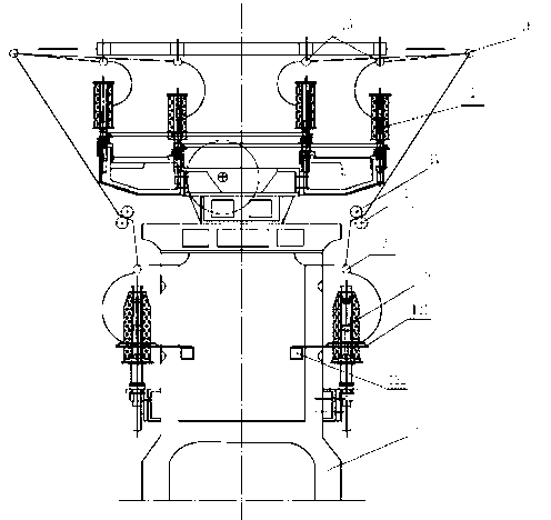
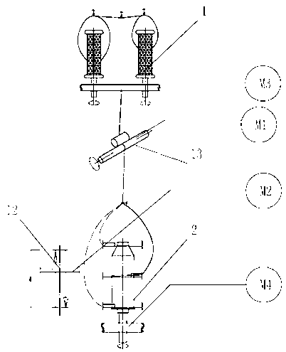

Image

  • Twisting and spooling combine
  • Twisting and spooling combine
  • Twisting and spooling combine

Examples


Embodiment 1

[0076] An integrated twisting machine, comprising an upper spindle assembly 1, a lower spindle assembly 2, and an introduction guide 3 for feeding the thread to the lower spindle assembly 2, the upper spindle assembly 1 guides the thread through the The silk device 3 is delivered to the lower spindle assembly 2, the lower spindle assembly 2 includes a bobbin 4, a rotating shaft 5 and a base 6, the rotating shaft 5 is provided with a base support member 7, and the base 6 is provided with There is a locking member 8, the base 6 is fixed on the rotating shaft 5 through the base support member 7, the bobbin 4 is sleeved on the rotating shaft 5, and the bobbin 4 is fixed on the base 6 through the locking member 8 superior.

[0077]In the present invention, the base 6 is provided with an inlaid cavity, and an inlaid core 61 is provided in the inlaid cavity, the locking member 8 is arranged on the inlay core 61, and the bobbin 4 is fixed on the inlay core 61 through the locking membe...

Embodiment 2

[0110] The difference from Implementation 1 is that: the length of the supporting ball protruding from the outer surface of the annular flange is 3 mm; there are three supporting balls on the upper annular flange and the lower annular flange, forming three points respectively. The positioning support structure; the outer diameter of the annular flange is 30mm, the width is 25mm, the distance between the two adjacent annular flanges is 85mm; the diameter of the supporting ball is 9mm. The locking member 8 is at least equally divided into five arc-shaped locking blocks 10 , and each locking block 10 is provided with an anti-slip protrusion 9 .

Embodiment 3

[0112] The difference from Implementation 1 and 2 is that: the length of the supporting ball protruding from the outer surface of the annular flange is mm; the supporting balls on the upper annular flange and the lower annular flange are three, respectively forming Three-point positioning support structure; the outer diameter of the annular flange is 30 mm, the width is 26 mm, and the distance between two adjacent annular flanges is 90 mm; the diameter of the supporting ball is 10 mm.

[0113] The locking member 8 is at least equally divided into eight arc-shaped locking blocks 10 , and each locking block 10 is provided with an anti-slip protrusion 9 .


PUM

PropertyMeasurementUnit
lengthaaaaaaaaaa
lengthaaaaaaaaaa
widthaaaaaaaaaa

Abstract

The invention discloses a twisting and spooling combine. The twisting and spooling combine comprises an upper spindle assembly, a lower spindle assembly, and a thread-guiding device conveying threads to the lower spindle assembly. The upper spindle assembly conveys the threads to the lower spindle assembly through the thread-guiding device. The lower spindle assembly comprises a winding tube, a rotary shaft and a base. A base support is disposed on the rotary shaft. The base is provided with a locking member and is fixed on the rotary shaft through the base support. The winding tube is sleeved on the rotary shaft and is fixed on the base through the locking member. The twisting and spooling combine requires a reeling step and a twisting step only. Twisted threads can be wound into a hard tube by the twisting step, a product required by a client is formed directly, and a soft cone is replaced. The threads wound by the lower spindle assembly are heavier and longer than threads wound by the prior art, the requirements of clients for long threads are well met, and the spooling step of winding the short threads into long threads is avoided. The twisting and spooling combine is low in cost and simple to operate.

Description

technical field [0001] The invention relates to a twisting machine, in particular to an integrated twisting machine and tube forming machine. Background technique [0002] The current twisting and barreling process includes: winding, twisting, and barreling. [0003] Winding refers to changing the package form of the silk thread, that is, to roll the cake-packed silk cake or tube (boundless package) into a package with edges, so that the raw material can obtain the package form and length (size) suitable for the next process. The traditional process is to wind with a high-speed winder. [0004] Twisting refers to the twisting process of twisting two or more strands of yarn to obtain the desired twist. The traditional process is to use a compound twisting machine for twisting. The compound twisting machine is divided into three parts: one is the upper rotating mechanism, which is mainly to add primary twist to the monofilament; the other is the wire feeding mechanism, which...

Claims


Application Information

Patent Timeline
Patent Type & Authority Applications(China)
IPC IPC(8): D01H1/36D01H7/02D01H7/10D01H1/24B65H75/02
Inventor 杨书磊杨学利刘涛
Owner GAOXIAN CHANGXIN LINE
Learn More