
Oil filling pipe assembly for engine

A technology for oil pipes and engines, which is used in lubricant conduit devices, adding/discharging lubricants, and lubricating parts, etc., can solve the problems of cumbersome strength reliability judgment, long development cycle of new products, and many welding parts, etc., to avoid High failure risk, lightweight and good corrosion resistance

Active Publication Date: 2013-01-09
WEIFANG BELEAD AUTOMOBILE PARTS
View PDF4 Cites 5 Cited by
  • Summary
  • Abstract
  • Description
  • Claims
  • Application Information

AI Technical Summary

Problems solved by technology

Among them, the oil filling pipe made of metal material is made of steel pipe with a wall thickness of 1.2-3mm. Due to the requirements of installing the cover and space bending, especially for the requirements of complex space bending and variable diameter pipe body, the pipe body needs to be segmented with different shapes It is welded, and the assembly and positioning of its cover and other components need to be welded or riveted to related structural parts. This structural product has complex structure, heavy weight, and high process cost. Due to the large number of welding parts, the risk of failure is high and the appearance is not beautiful; plastic materials The refueling oil pipe has achieved the purpose of light weight, but for the complex space bending structure, its application is limited by the conditions of high temperature resistance and corrosion resistance, and strict and tedious strength and reliability judgments must be carried out for each product, resulting in new products. Long development cycle

Method used


Image

  • Oil filling pipe assembly for engine
  • Oil filling pipe assembly for engine

Examples


Embodiment Construction

[0024] The present invention will be further described below in conjunction with the accompanying drawings and embodiments.

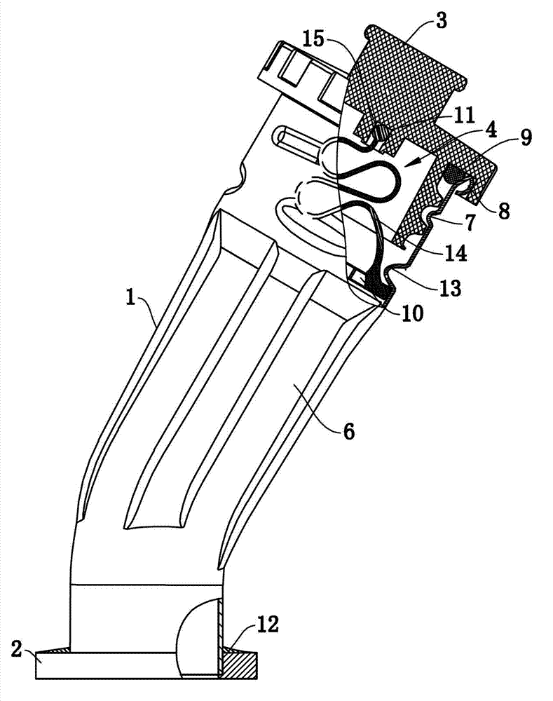
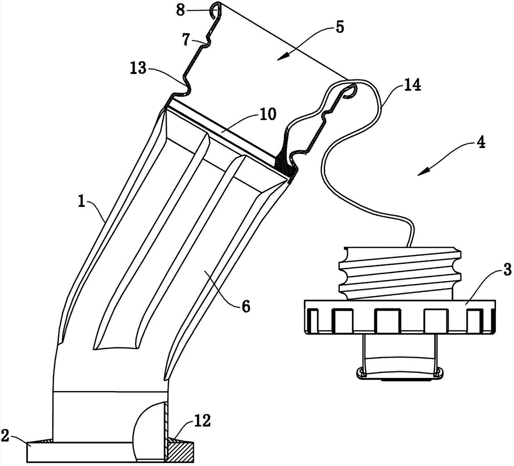
[0025] Such as figure 1 and figure 2 Commonly shown, the engine oil pipe assembly includes the oil pipe body 1, the flange 2, the pipe cover 3 and the connecting part 4. One end of the oil pipe body 1 is provided with a nozzle 5, and the other end of the oil pipe body 1 is connected to the flange 2. The nozzle and the cap 3 are connected by threads, and the oil pipe body 1 and the cap 3 are connected by a connecting part 4. The oil pipe body 1 is a thin-walled stainless steel pipe processed by hydroforming, and the wall thickness of the thin-walled stainless steel pipe is 0.5mm-1mm. The pipe wall of the tubing body 1 is provided with four concave-convex reinforcing ribs 6, and the concave-convex reinforcing ribs 6 improve the strength of the tubing body 1, so that under the condition of satisfying the same structural strength as that of the prior art...


PUM


Abstract

The invention discloses an oil filling pipe assembly for an engine, which comprises an oil pipe main body, wherein a pipe opening is arranged at one end of the oil pipe main body; a flange is connected with the other end of the oil pipe main body; a pipe cap is in threaded connection with the pipe opening; and the oil pipe main body is a thin-wall stainless pipe which is formed through hydraulic molding processing. The oil filling pipe assembly for the engine has the advantages that the lightweight product is realized, the manufacturing cost is lowered, the product reliability is increased and the attractiveness of the appearance of the product is increased.

Description

technical field [0001] The invention relates to the technical field of engines, in particular to an engine fuel filler pipe assembly. Background technique [0002] The engine must be equipped with an oil filling port, which is usually achieved by setting a fuel oil pipe assembly at a certain position on the cylinder block or other structural parts that communicate with the oil pan. At the same time, the oil pipe assembly must be under 0.1MPa pressure No leakage occurs. [0003] The oil filler pipe in the prior art consists of a pipe body of metal material and a pipe body of plastic material. Among them, the oil filling pipe made of metal material is made of steel pipe with a wall thickness of 1.2-3mm. Due to the requirements of installing the cover and space bending, especially for the requirements of complex space bending and variable diameter pipe body, the pipe body needs to be segmented with different shapes It is welded, and the assembly and positioning of its cover a...

Claims


Application Information

Patent Timeline
Patent Type & Authority Applications(China)
IPC IPC(8): F01M11/04F01M11/02
Inventor 易斌何海林彭东南余达毕明松蒲博伟高林玉
Owner WEIFANG BELEAD AUTOMOBILE PARTS
Learn More