Organic el illumination device
A lighting device, an organic technology, applied in lighting devices, cooling/heating devices for lighting devices, lighting and heating equipment, etc., can solve the problems of destroying protective films, enlarging cathode and anode ITO short circuits, short circuits, etc.
- Summary
- Abstract
- Description
- Claims
- Application Information
AI Technical Summary
Problems solved by technology
Method used
Image
Examples
Embodiment 1)
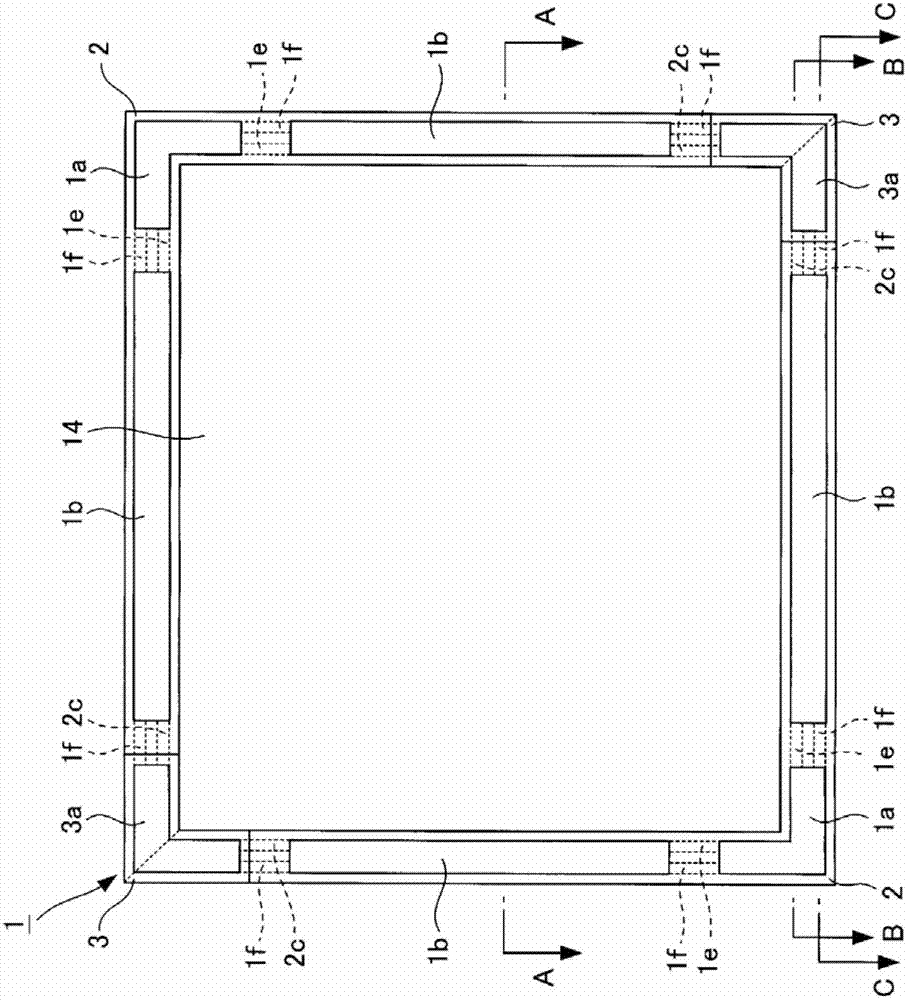
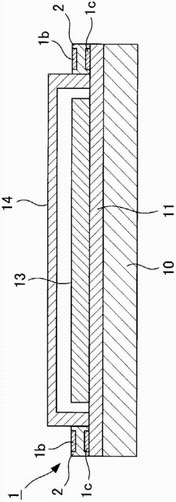
[0132] Hereinafter, an organic EL lighting device according to a first embodiment of the present invention will be described.
[0133] First, the structure of the organic EL lighting device of this embodiment will be briefly described.
[0134] The organic EL lighting device of this embodiment is the same as the existing organic EL lighting device. Figure 39 with Figure 40 The four sides on the shown glass substrate 10 have anode terminal electrodes 11 respectively, and the four corners on the glass substrate 10 respectively have cathode terminal electrodes 12, and a sealed container 14 is provided on the glass substrate 10 to cover the organic EL element 13, This prevents performance degradation of the organic EL element 13 due to oxygen, water, and the like. In addition, in this embodiment, the glass substrate 10 is used as the substrate, but other materials such as plastic, metal, and ceramics can also be used as the substrate.
[0135] figure 1 It is a plan view of t...
Embodiment 2)
[0160] Hereinafter, an organic EL lighting device according to a second embodiment of the present invention will be described.
[0161] Figure 7 It is a plan view of the organic EL lighting device of this embodiment. Figure 8 yes Figure 7 Cross-sectional view of the section shown in A-A.
[0162] Such as Figure 7 , 8 As shown, the structure of the organic EL lighting device of this embodiment is basically the same as that of the organic EL lighting device of the first embodiment, as shown in Figure 7 , 8 As shown, the difference is that the size of the wiring board 1 is enlarged. This eliminates the need for an operator to directly touch the anode terminal electrode 11 , the cathode terminal electrode 12 , the end surface of the glass substrate 10 , and the like. In addition, in this embodiment, the outer circumference of the wiring board 1 is larger than the outer circumference of the glass substrate 10 by about 0.5 to 3.0 mm.
[0163] However, in the conventiona...
Embodiment 3)
[0167] Hereinafter, an organic EL lighting device according to a third embodiment of the present invention will be described.
[0168] Figure 9 It is a plan view of the organic EL lighting device of this embodiment. Figure 10 yes Figure 9 Cross-sectional view of the section shown in A-A. In addition, although Figure 9 , 10 The connector is omitted in , but the connector is actually installed.
[0169] Such as Figure 9 , 10 As shown, the structure of the organic EL lighting device of this embodiment is basically the same as the structure of the organic EL lighting device of the first embodiment. An anode power supply terminal portion 4a protrudes from the anode wiring 1a, and a cathode power supply terminal portion 4b protrudes from the cathode wiring 1b. This way, you don't have to use Figure 42 With the anode lead-out wire 22 and cathode lead-out wire 23 shown, the connector 24 can be directly connected to the anode power supply terminal part 4a and the cathode...
PUM
 Abstract
Description
Claims
Application Information
 - R&D
- Intellectual Property
- Life Sciences
- Materials
- Tech Scout
- Unparalleled Data Quality
- Higher Quality Content
- 60% Fewer Hallucinations
Browse by: Latest US Patents, China's latest patents, Technical Efficacy Thesaurus, Application Domain, Technology Topic, Popular Technical Reports.
© 2025 PatSnap. All rights reserved.Legal|Privacy policy|Modern Slavery Act Transparency Statement|Sitemap|About US| Contact US: help@patsnap.com


