Eureka AIR delivers breakthrough ideas for toughest innovation challenges, trusted by R&D personnel around the world.

Steelmaking residual heat step recycling method

A cascade recovery and waste heat technology, which is applied in the field of utilization of ironmaking waste heat and waste energy in the iron and steel industry, can solve the problems of cascade recovery and high-efficiency utilization of waste heat that cannot be systematically solved, and achieve the effects of improving comprehensive utilization efficiency, optimizing system energy structure, and compact structure

Active Publication Date: 2013-01-02
SHOUGANG CORPORATION
View PDF6 Cites 24 Cited by
  • Summary
  • Abstract
  • Description
  • Claims
  • Application Information

AI Technical Summary

Problems solved by technology

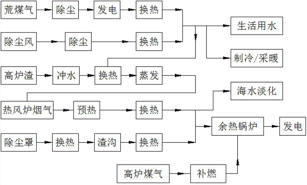
[0005] The above method focuses on the recovery and utilization of individual waste heat in the ironmaking system, but it cannot systematically solve the problem of cascaded recovery and efficient utilization of waste heat. Therefore, the present invention proposes an ironmaking The method of cascaded recovery and efficient utilization of low-grade waste heat in the system, through series-parallel connection of different grades of waste heat, graded utilization of waste heat and waste energy resources, reduces energy consumption in the ironmaking process, and realizes energy saving and emission reduction in the ironmaking system

Method used

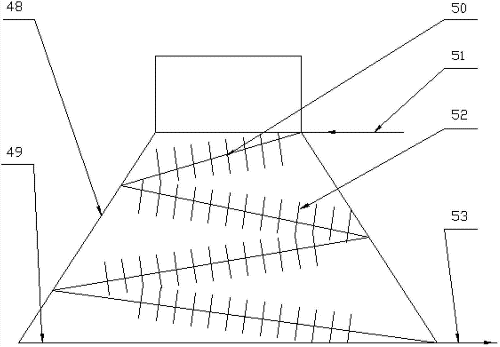

Image

  • Steelmaking residual heat step recycling method
  • Steelmaking residual heat step recycling method
  • Steelmaking residual heat step recycling method

Examples


Embodiment Construction

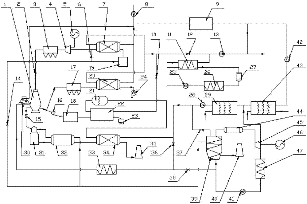
[0030] see Figure 2~3 , the method for cascaded recovery and utilization of ironmaking waste heat provided by the embodiment of the present invention, the specific implementation method is as follows.

[0031]The raw gas from the blast furnace 1 passes through the cut-off valve 2 of the gas main pipe, enters the gas dry dust collector 3 for dry low-pressure pulse dust removal, and then enters the residual pressure turbine 4 to drive the generator 5 for residual pressure power generation. After the residual pressure power generation, the gas It is divided into two paths, one path first enters the gas waste heat exchanger 7, and enters the gas cabinet 19 after waste heat recovery, and the other path passes through the gas branch pipe regulating valve 6, and after being merged with the gas of the previous path, the flow is adjusted by the gas main regulating valve 14, and the path passes through After the gas heat pipe heat exchanger 32 is preheated, it enters the hot blast stov...


PUM


Abstract

The invention discloses a steelmaking residual heat step recycling method. The invention belongs to the technical field of steel industry iron-making residual heat and residual energy utilization. The method is adopted under a condition for further utilizing iron-making low-grade residual heat, and comprises step recycling and high-efficiency utilizations of blast furnace gas residual heat, dust removal air residual heat, water slag residual heat, hot air furnace low-temperature flue gas waste heat, and dust cover and slag ditch residual heat. According to the technical scheme, blast furnace gas residual heat and dust removal air residual heat obtained after furnace top residual pressure power generation are connected in parallel, and are supplied for domestic water, cooling, or heating. Recycled water slag residual heat and flue gas residual heat obtained after hot air furnace gas heat exchanger are connected in parallel, and are used for supplying a heat source for low-temperature seawater desalination. Recycled dust cover residual heat and slag ditch surface radiation heat are connected in parallel, and are supplied for blast furnace gas supplementary firing residual heat boiler power generation. After powder generation, high-temperature seawater desalination is realized by a steam method. Cooling water and domestic water are treated and are adopted as inlet water replenishment. Through step recycling and graded utilization of the low-grade residual heat and residual energy, steel system comprehensive energy consumption can be reduced to a maximal extent, and energy resource reasonable utilization and comprehensive optimized utilization can be realized.

Description

technical field [0001] The invention relates to the technical field of utilization of ironmaking waste heat and energy in the iron and steel industry, in particular to a method for cascaded recovery and efficient utilization of ironmaking system waste heat, in the case of further reducing the comprehensive energy consumption of iron and steel and realizing efficient recycling and utilization of ironmaking waste heat and energy in the iron and steel industry use. Background technique [0002] The iron and steel industry is a high energy consumption and high pollution industry, and it is the focus of the country's energy conservation and emission reduction. According to statistics, the total amount of waste heat and energy produced per ton of steel in iron and steel enterprises is about 288kgce / t, accounting for about 40% of the comprehensive energy consumption per ton of steel. In order to further reduce the comprehensive energy consumption of iron and steel and improve the ...

Claims


Application Information

Patent Timeline
IPC IPC(8): C21B5/06F27D17/00
CPCY02P10/25
Inventor 陈冠军张效鹏郭之明杨小龙张延平沈海波
Owner SHOUGANG CORPORATION
Why Eureka
Eureka Blog
Learn More