
Directly moving type high-flow directional flow servo valve and control system using servo valve

A large-flow, direct-acting technology, applied in the direction of servo motor components, fluid pressure actuators, mechanical equipment, etc., can solve the problems of long adjustment time and poor stability of the hydraulic system, and achieve no temperature zero drift, zero position The effect of accurate positioning and accurate control precision

Inactive Publication Date: 2012-12-19
北京润菲利德科技有限公司
View PDF9 Cites 11 Cited by
  • Summary
  • Abstract
  • Description
  • Claims
  • Application Information

AI Technical Summary

Problems solved by technology

[0004] For this reason, the technical problem to be solved by the present invention is that the adjustment time of the zero position positioning of the existing direct-acting large flow directional flow servo valve is relatively long, and when the zero position is adjusted, the stability of the hydraulic system is relatively poor, and further provides A directional flow servo valve with fast zero position positioning adjustment speed

Method used


Image

  • Directly moving type high-flow directional flow servo valve and control system using servo valve
  • Directly moving type high-flow directional flow servo valve and control system using servo valve
  • Directly moving type high-flow directional flow servo valve and control system using servo valve

Examples


Embodiment 1

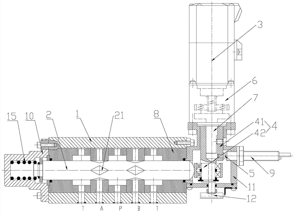
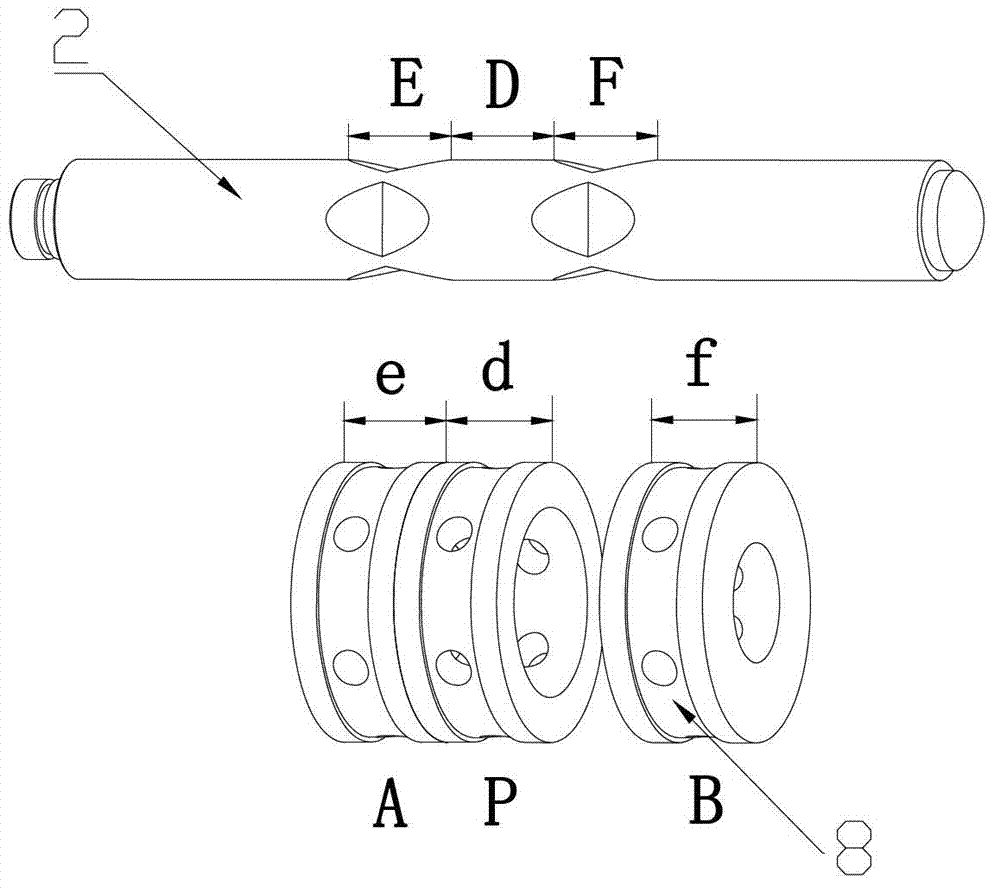
[0030] figure 1 It is a direct-acting large flow directional flow servo valve disclosed in the present invention, which includes a valve body 1, a valve core 2 is arranged in the valve body 1; a servo motor 3 for controlling the movement of the valve core 2, and a The cam mechanism between the servo motor 3 and the valve body 1 is provided in the cam box 11, and the cam box 11 is sealed and connected with the valve body 1 and the servo motor 3 respectively. The cam mechanism includes: a camshaft 4 driven by the servo motor 3, the camshaft 4 includes an eccentric section 42 and a driving section 41, and one end of the spool 2 is pressed against the axial surface of the eccentric section 42 On the axial surface of the driving section 41, a zero induction head 5 is provided; on the cam box 11, an induction sensor 9 is provided corresponding to the zero induction head 5, and the induction sensor 9 is used to connect to the controller , the controller receives the signal from the ...

Embodiment 2

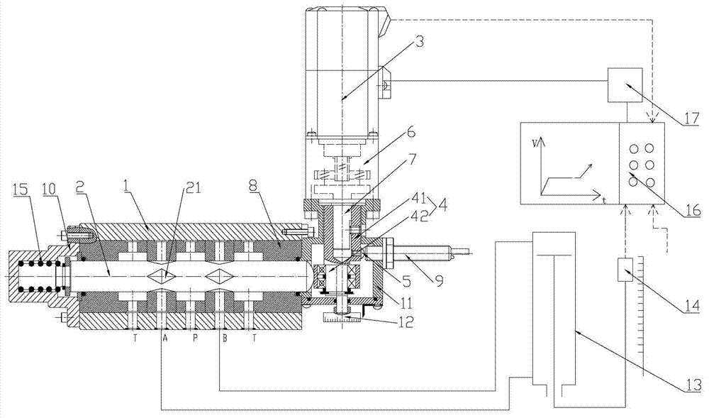
[0047] like Figure 4 As shown, adopt one described controller 16, three described drivers 17 and three flow servo valves described in Embodiment 1, three described hydraulic actuators 13: hydraulic cylinder (oil motor), and three One position detection device 14: a linear encoder (rotary encoder) can realize the interpolation linkage real-time control of three hydraulic cylinders (oil motors) for spatial curves.

Embodiment 3

[0049] like Figure 5 As shown, using one controller 16, six drivers 17 and six servo valves in Embodiment 1, six hydraulic actuators 13: performing hydraulic cylinders (oil motors), six positions Detection device 14: linear encoder (rotary encoder), can realize the parallel servo control of the six-degree-of-freedom hydraulic heavy-duty manipulator or processing manipulator, and create a new field of hydraulic servo machinery application in super-large heavy industrial equipment and military equipment. Multi-axis linkage hydraulic servo control. Such as: radar tracking, satellite navigation, unmanned driving, remote reduction of ships, automatic aiming and launching of ship-borne missiles and other equipment hydraulic servo control.

[0050] In other embodiments, the position detection device 14 can also be a displacement sensor for detecting displacement. At the same time, the hydraulic actuator 13 can also use a hydraulic motor according to the application. At this time, t...


PUM


Abstract

The invention discloses a directly moving type high-flow directional flow servo valve and a control system using the servo valve. A valve core of the servo valve is pushed by a cam shaft driven by a servo motor; the cam shaft comprises an eccentric section and a driving section; one end of the valve core is pressed and leaned against a shaft surface of the eccentric section; a zero position sensing head is arranged on the shaft surface of the driving section; an inductive sensor which is matched with the zero position sensing head is arranged on a cam box; the inductive sensor is connected with a controller; and the controller is used for receiving a signal of the inductive sensor, controlling the servo motor to rotate back and forth in a small scope and performing the zero position positioning on the valve core. The servo valve is high in response speed and high in control precision. Meanwhile, the zero position positioning of the valve core is high in accuracy, is free from temperature null shift and is high in repeating precision. The adjusting time for the zero position positioning is short and a hydraulic system is relative stable when the zero position is adjusted.

Description

technical field [0001] The invention belongs to the technical field of design and manufacture of servo valves, and in particular relates to a direct-acting large flow directional flow servo valve and a control system using the servo valve. Background technique [0002] Most of the existing directional flow servo valves are electro-hydraulic proportional direct-acting or pilot-operated servo valves, which are driven by a torque motor or a moving coil electromagnet to drive a single-nozzle baffle, a double-nozzle baffle, and a jet nozzle structure. The pilot valve is amplified by two and three stages. The hydraulic pressure difference drives the large flow spool valve spool (large diameter spool) to make axial displacement, and the axial displacement measures the zero position, displacement direction and displacement of the spool through a differential transformer (displacement sensor). The spool response speed is low, the displacement control precision is low, the repeatabil...

Claims


Application Information

Patent Timeline
Patent Type & Authority Applications(China)
IPC IPC(8): F15B13/02F15B13/044F15B15/28
Inventor 孙勇
Owner 北京润菲利德科技有限公司
Learn More