
Photoacoustic tomography system combined with acoustical transmission reflector and imaging method thereof

An imaging system and a technology of photoacoustic tomography, which are applied in the fields of radiological diagnosis instruments, medical science, diagnosis, etc., can solve the problems of unsatisfactory laser irradiation method, inability to irradiate biological tissue horizontally and uniformly, and inability to adjust incident light, etc. , to achieve the effect of being conducive to ultrasonic penetration and low loss

Inactive Publication Date: 2012-12-19
PEKING UNIV
View PDF8 Cites 10 Cited by
  • Summary
  • Abstract
  • Description
  • Claims
  • Application Information

AI Technical Summary

Problems solved by technology

[0004] However, in the current PAT imaging, the incident light cannot be adjusted so that it can enter uniformly and horizontally. The illumination methods of the prior art, such as the two-side illumination method, are blocked by the transducer and the illumination light field on the surface of the animal body is not stable. Inhomogeneous, so existing laser irradiation methods for PAT are not ideal for irradiating biological tissue horizontally and uniformly without compromising acquisition

Method used


Image

  • Photoacoustic tomography system combined with acoustical transmission reflector and imaging method thereof
  • Photoacoustic tomography system combined with acoustical transmission reflector and imaging method thereof
  • Photoacoustic tomography system combined with acoustical transmission reflector and imaging method thereof

Examples


Embodiment Construction

[0025] Below in conjunction with accompanying drawing, through embodiment, further illustrate the present invention.

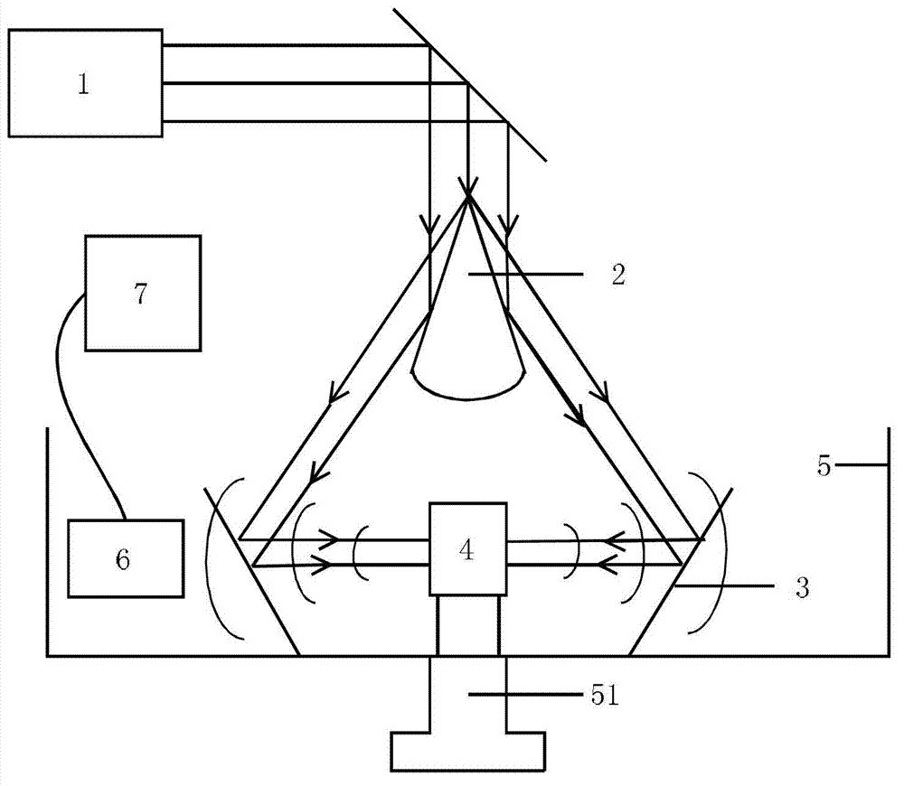
[0026] Such as figure 1 As shown, the photoacoustic tomography system combined with the sound-transmitting mirror of the present invention includes: a laser light source 1 , a conical mirror body 2 , a sound-transmitting mirror 3 , an animal table 4 , a water tank 5 , a detector 6 and a computer 7 . Water tank 5 is installed on the lifting platform 51.

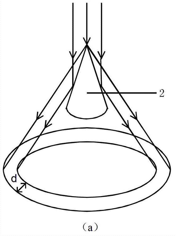
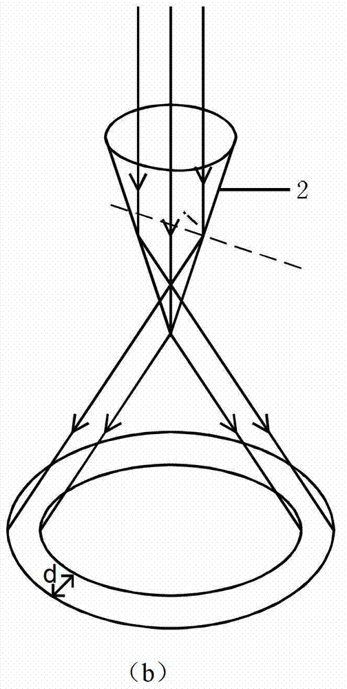
[0027] figure 2 The schematic diagram of the optical path of the incident light reflected by the conical mirror body of the present invention. Such as figure 2 As shown in (a), the conical mirror body 2 adopts a conical reflector. The pulse laser enters the conical reflector vertically and is reflected by the outer surface of the conical reflector to form a circular beam. The radius of the circular beam is along the The propagation direction increases with the propagation distance, and the width d of the...


PUM


Abstract

The invention discloses a photoacoustic tomography system combined with an acoustical transmission reflector and an imaging method of the photoacoustic tomography system combined with the acoustical transmission reflector. The photoacoustic tomography system comprises a laser light source, a conscope body, the acoustical transmission reflector, an animal platform, a water tank, a detector and a computer. The acoustical transmission reflector is utilized, and a metal-coated LDPE (Low-Density Polyethylene) material is adopted as the material of the acoustical transmission reflector, so that acoustic impedance similar to that of water is obtained, and further, remarkable ultrasonic reflection is not generated at a water-medium interface; and the material is thin, so that attenuation of ultrasonic waves in the material is lower, loss of the acoustical transmission reflector on the ultrasonic waves is very small, and the transmission of the ultrasonic waves is more convenient. Further, the conscope body is combined with an inverted cone-shaped acoustical transmission reflector, light is focused in a horizontal plane and irradiated onto an animal body to form 360-degree horizontal and uniform irradiation on the animal body, and a uniform and stable light field can be formed in the animal body, so that a reconstructed image can more accurately reflect physiological structure function information in the animal body when the detector is used for detection.

Description

technical field [0001] The invention belongs to photoacoustic tomography technology, in particular to a photoacoustic tomography system combined with a sound-transmitting mirror and an imaging method thereof. Background technique [0002] Photoacoustic Tomography (Photoacoustic Tomography) PAT is a tomographic imaging technology based on the photoacoustic effect. This imaging technique is non-invasive and combines the high contrast of optical imaging with the high resolution of ultrasound imaging to obtain higher resolution images in deeper tissues. [0003] Since the photoacoustic signal attenuates rapidly in the air, when PAT imaging, the measured object is placed in water or other ultrasonic coupling medium to reduce the attenuation of the photoacoustic signal. In PAT imaging, pulsed laser light acts on the animal body, different components in the animal body absorb the laser light, and generate ultrasonic signals based on the principle of photoacoustic effect. The ultr...

Claims


Application Information

Patent Timeline
IPC IPC(8): A61B6/02
Inventor 李长辉邓梓健任秋实
Owner PEKING UNIV
Learn More