Wick structure for vapor chamber
A liquid absorbent core and soaking plate technology, applied in indirect heat exchangers, lighting and heating equipment, cooling/ventilation/heating renovation, etc., can solve the problems of large flow resistance, small capillary pressure, large capillary pressure, etc. Improve heat dissipation efficiency, reduce flow resistance, and increase the effect of capillary suction
- Summary
- Abstract
- Description
- Claims
- Application Information
AI Technical Summary
Problems solved by technology
Method used
Image
Examples
Embodiment 1
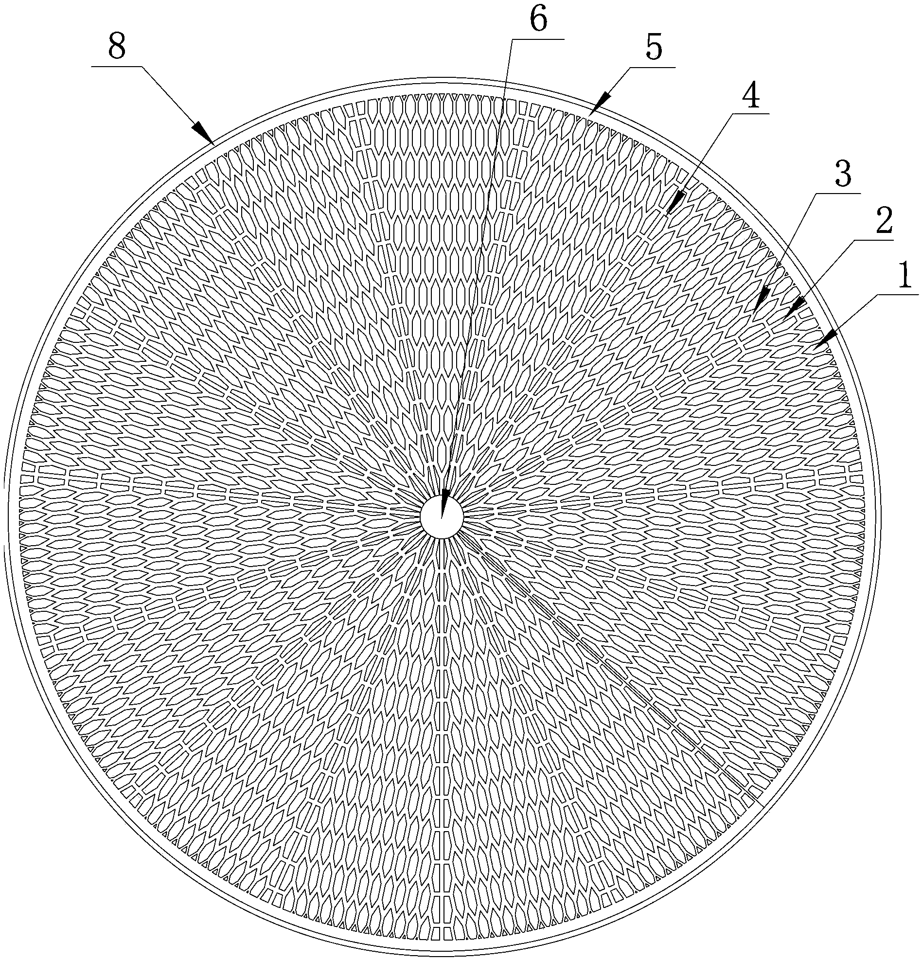
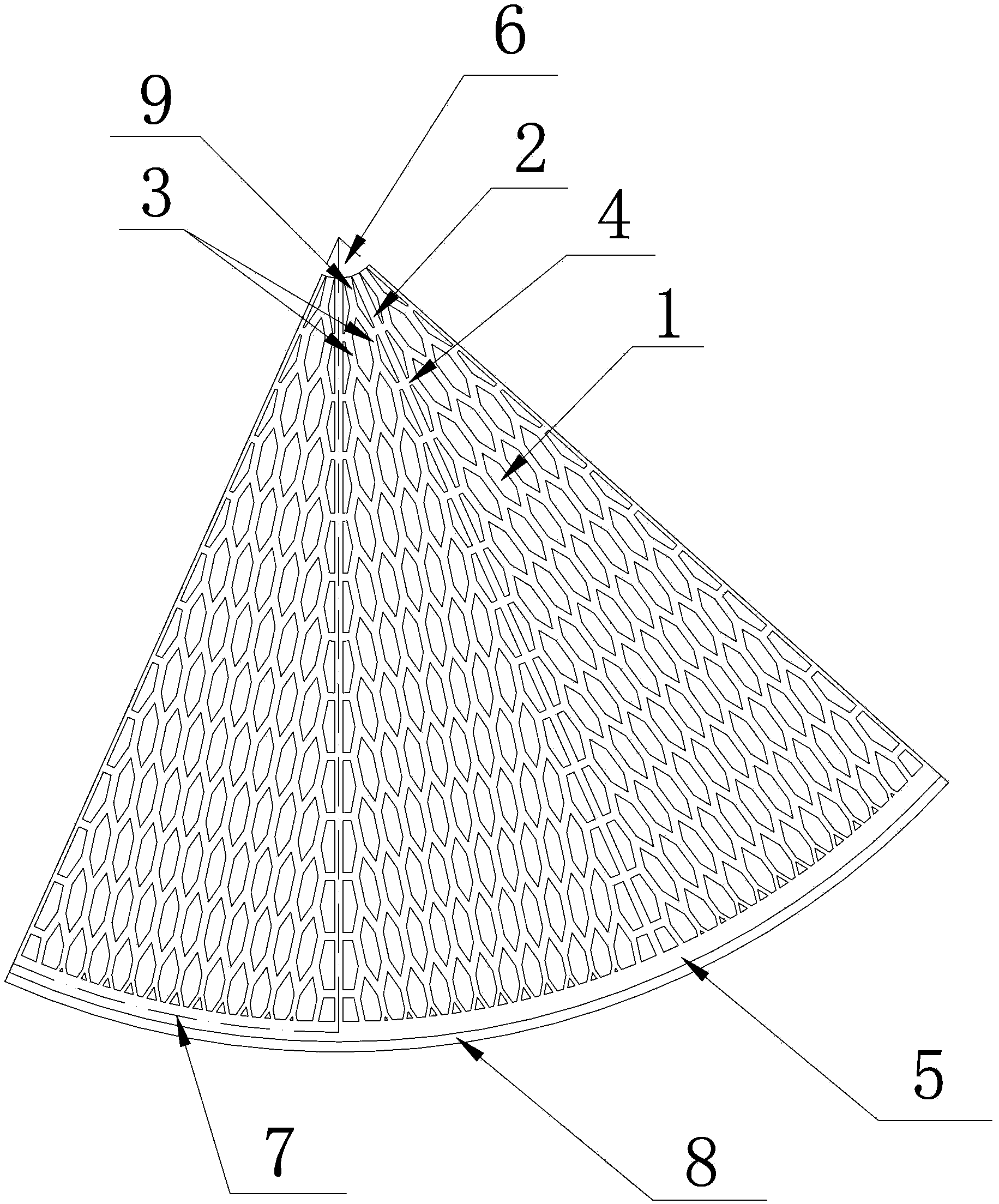
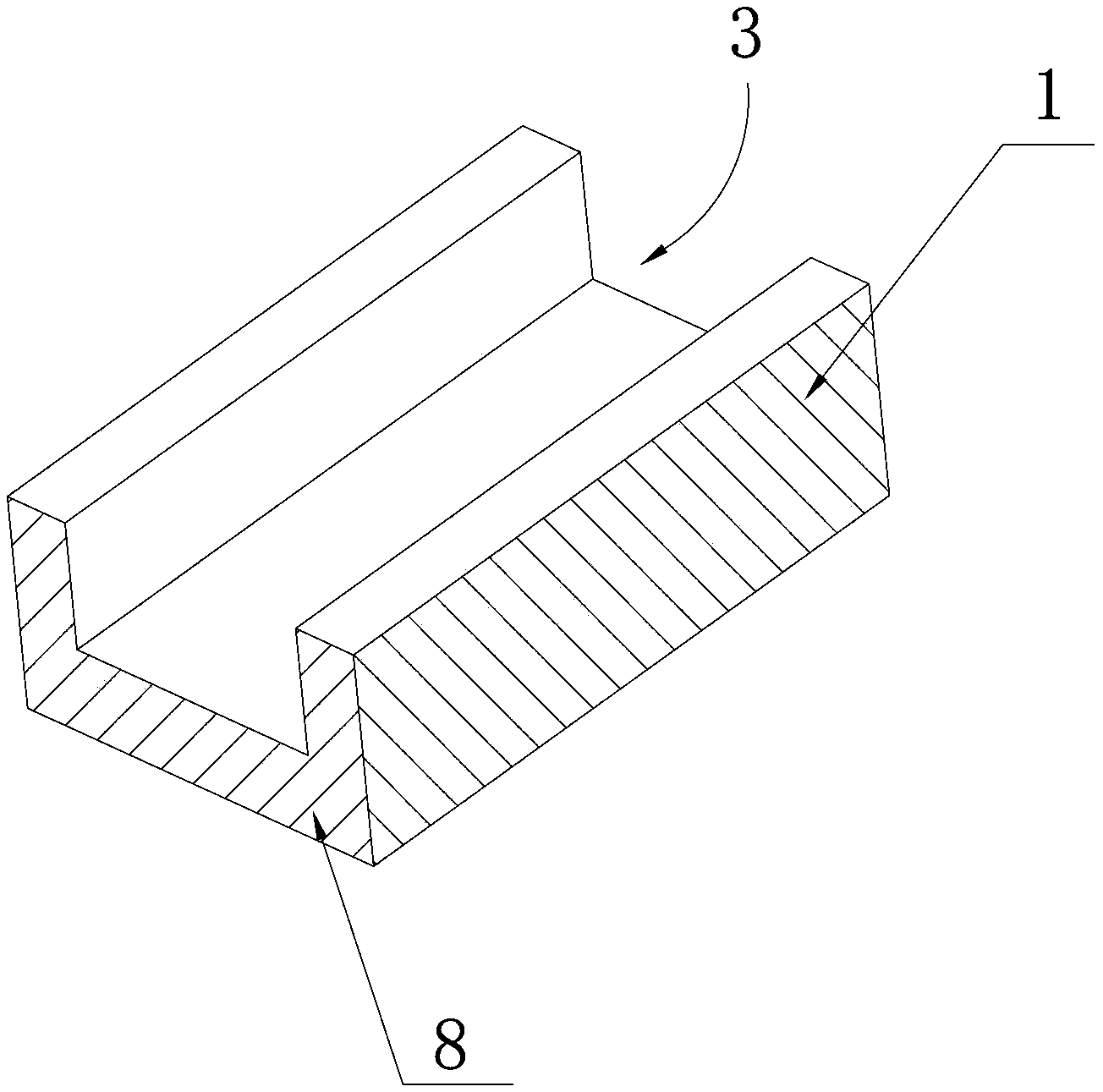
[0038] see Figure 1 ~ Figure 4 The liquid-absorbing core structure of the vapor chamber of this embodiment is arranged on a disc-shaped vapor chamber shell 8 made of copper. The fan-shaped condensation zone 7. Each condensing zone 7 is composed of a 12-level channel structure formed by branching outwards from the starting channel 9 at the center. Among them, the starting channel 9 is zero-level, and the zero-level bifurcation point I is divided into two, so that the first level has two thin channels 3, and the angle between the two bifurcated thin channels 3 is 45° , that is, the bifurcation angle θ 1 is 45°, and the two bifurcated thin channels 3 are bent into a parallel state and extend outward; the bifurcation points II of the two thin channels 3 of the first stage are divided into two, and the bifurcation angle θ 2 It is also 45°. Among the four bifurcated thin channels 3, the two in the middle intersect and merge into one, so that the second stage has three thin chann...
Embodiment 2
[0046] see Figure 7 , in this embodiment, each condensation zone 7 is divided into a multi-stage channel structure from the center to the outside, and the stages are separated by concentric arc-shaped channels 11, and the first stage is formed by bifurcating the starting channel 9 Two thin channels 3 are formed, and the bifurcation angle θ is 60°; the two thin channels 3 of the first stage extend outward and intersect with the arc-shaped channel 11 between the first stage and the second stage, and at each intersection point It is bifurcated into two thin channels 3 to form the second stage, and the bifurcation angle β is 50°; the thin channel 3 of the second stage extends outward and connects with the arc-shaped channel 11 between the second stage and the third stage Intersect, and each intersection bifurcates into two thin channels 3, forming the third level, the bifurcation angle γ is 40°; the third level of thin channels 3 extends outward and connects with the The arc-sha...
Embodiment 3
[0050] see Figure 8 , the difference between the network channel structure of this embodiment and Embodiment 1 is that in this embodiment, the four thin channels 3 separated from two adjacent thin channels 3 at the same level do not intersect, and the two in the middle The thin channels 3 communicate with each other through horizontal channels 12 , and the thin channels 3 and the horizontal channels 12 of the above-mentioned levels communicate with each other to form a network channel structure.
[0051] In this embodiment, the bifurcation angles θ of the narrow channels 3 at all levels are 45°, the ratio of the width of the narrow channels 3 of the latter stage to the width of the narrow channels 3 of the previous stage is 0.8, and the fine grooves of the latter stage The ratio of the length of the track 3 to the length of the previous fine channel 3 is 0.8.
[0052] Embodiments other than the above in this embodiment are the same as in Embodiment 1.
[0053] The above is ...
PUM
 Abstract
Description
Claims
Application Information
 - Generate Ideas
- Intellectual Property
- Life Sciences
- Materials
- Tech Scout
- Unparalleled Data Quality
- Higher Quality Content
- 60% Fewer Hallucinations
Browse by: Latest US Patents, China's latest patents, Technical Efficacy Thesaurus, Application Domain, Technology Topic, Popular Technical Reports.
© 2025 PatSnap. All rights reserved.Legal|Privacy policy|Modern Slavery Act Transparency Statement|Sitemap|About US| Contact US: help@patsnap.com


