
Photovoltaic grid-connected micro-inverter system

A micro-inverter, photovoltaic technology, applied in photovoltaic power generation, climate change adaptation, single-grid parallel feeding arrangement, etc., can solve problems such as energy waste of solar panel arrays, dangerous high-voltage DC circuits, system failures, etc., to achieve convenient The effect of capacity expansion and maintenance, overcoming weak links, and low failure rate

Inactive Publication Date: 2012-11-28
HUAZHONG UNIV OF SCI & TECH
View PDF6 Cites 11 Cited by
  • Summary
  • Abstract
  • Description
  • Claims
  • Application Information

AI Technical Summary

Problems solved by technology

"Centralized" grid-connected inverters not only have dangerous high-voltage DC circuits, but also require the components to be as consistent as possible during installation, making it difficult to change the array structure and expand capacity
Moreover, the "centralized" grid-connected inverter has poor adaptability to the actual environment. In actual applications, when internal and external unfavorable conditions such as shadow occlusion, cloud changes, dirt accumulation, and uneven component efficiency attenuation occur, individual problematic components will affect other components of the system. , which significantly reduces the overall system efficiency
Failure of a single panel can lead to failure of the entire system
When the centralized inverter fails, the energy generated by the entire solar panel array will be wasted and the energy loss will be large

Method used


Image

  • Photovoltaic grid-connected micro-inverter system
  • Photovoltaic grid-connected micro-inverter system
  • Photovoltaic grid-connected micro-inverter system

Examples


Embodiment Construction

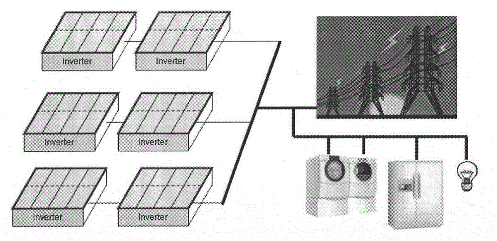
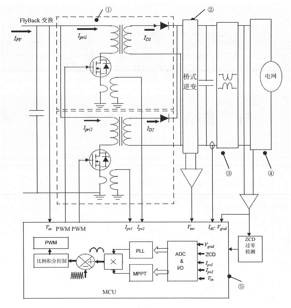
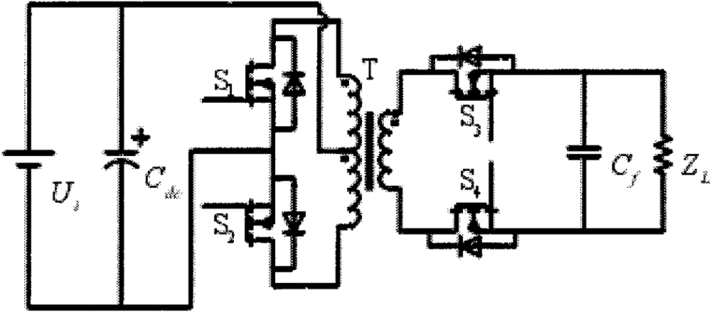
[0022] Such as Figure 1 to Figure 11 As shown, the specific implementation method is: the FlyBack conversion circuit ① uses the structure of the push-pull circuit topology to perform high-frequency conversion of the current source, and the bridge inverter circuit ② performs power frequency inversion. It can be seen that the circuit structure is simple: the primary side of the transformer is two push-pull high-frequency SPWM switching tubes, which perform sinusoidal modulation of the incoming current and MPPT control; the transformer is used for isolation in the middle; the two branches of the secondary side each work half frequency cycle. Among them, each branch has a switch tube controlled by power frequency, and the two switch tubes on the secondary side are complementary to conduct and synchronized with the power grid.

[0023] According to the polarity of the output voltage and the secondary inductor current, the circuit has four operating modes. Each working mode is eq...


PUM


Abstract

The invention relates to a photovoltaic grid-connected micro-inverter system. The input voltage and current of a single solar panel component are detected, a Flyback topological circuit structure is used for obtaining the maximum energy output of solar panels by utilizing a maximum power point tracking (MPPT) technology to design a 150 to 250W photovoltaic grid-connected micro-inverter, each solar panel is subjected to independent component inversion, and alternating current bus voltage is directly output, so that maximum power and maximum energy output can be obtained from each component, and the maximum energy conversion efficiency of the whole solar panel array can be achieved. A high-cost and highly-risky high-voltage direct current circuit is eliminated, and the influence of an independent defective component on the other components is avoided, so that the overall efficiency of the system cannot be remarkably reduced, and the shortcomings of the conventional centralized inverter are overcome. The system has the characteristics of low failure rate, high flexibility and convenience for maintenance, and is easy to mount.

Description

technical field [0001] The invention relates to the field of photovoltaic power generation, in particular to a micro-power inverter system that directly performs grid-connected inversion on a photovoltaic panel assembly. Background technique [0002] At present, the commonly used structure of photovoltaic grid-connected inverter is centralized. The so-called "centralized" means that a number of photovoltaic solar panels are connected in parallel and connected in series to form an array to generate high-power DC voltage, and then the DC power is converted into a sine wave with the same frequency and phase as the grid through a grid-connected inverter. The wave current is fed into the grid. "Centralized" grid-connected inverters not only have dangerous high-voltage DC circuits, but also require the components to be as consistent as possible during installation, making it difficult to change the array structure and expand capacity. Moreover, the "centralized" grid-connected i...

Claims


Application Information

Patent Timeline
IPC IPC(8): H02J3/38H02M7/538H02M7/5395
CPCY02E10/563Y02A30/60Y02E10/56
Inventor 彭刚
Owner HUAZHONG UNIV OF SCI & TECH
Learn More