Low-temperature co-fired ceramic stacking protective element and manufacturing method thereof

A technology of low-temperature co-fired ceramics and protection components, which is used in electrical components, fuse manufacturing, emergency protection devices, etc., can solve the problems of difficult to control the length of the fuse link, poor consistency of the fusing characteristics, and difficult to control the size of the micro-hole, so as to improve the design The effect of specification limit, good size consistency, and low power consumption

Active Publication Date: 2014-12-10
NANJING SART SCI & TECH DEV
View PDF7 Cites 0 Cited by
  • Summary
  • Abstract
  • Description
  • Claims
  • Application Information

AI Technical Summary

Problems solved by technology

However, this structure has obvious disadvantages: the micro-cavities are prone to deformation during product stacking and sintering, making it difficult to control the size of the micro-cavities, and the size of the micro-cavities is also limited; The effect of the downward depression makes it difficult to control the length of the fuse link, so that the consistency of the fusing characteristics of the final product will become poor

Method used


Image

  • Low-temperature co-fired ceramic stacking protective element and manufacturing method thereof
  • Low-temperature co-fired ceramic stacking protective element and manufacturing method thereof
  • Low-temperature co-fired ceramic stacking protective element and manufacturing method thereof

Examples


Embodiment Construction

[0031] The present invention will be described in detail below in conjunction with the accompanying drawings and embodiments.

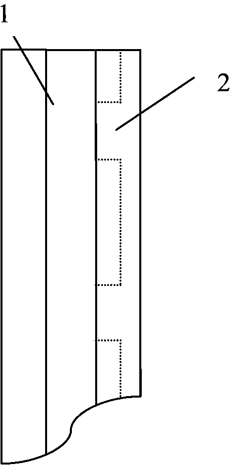
[0032] An embodiment of a low temperature co-fired ceramic stack protection element: as Figure 13 A low temperature co-fired ceramic stack protection element 4 shown includes a ceramic substrate 1 , a melt layer 3 and a terminal electrode 5 . Such as figure 1 As shown, the ceramic substrate 1 is formed by stacking ceramic diaphragms 11; the ceramic diaphragm 11 is formed by casting process of LTCC ceramic slurry; as figure 2 , image 3 As shown, a punching groove 2 is provided on the ceramic substrate 1, such as Figure 4 As shown, the stamping groove 2 is filled with LTCC porous ceramic slurry 21 or pore-forming agent slurry 22 through a thick film printing process; the melt layer 3 is composed of an LTCC ceramic diaphragm 11 and an electrode pattern 31, as Figure 5 As shown, the electrode pattern 31 includes two parts, the lead-out electrode...


PUM


Abstract

The invention relates to a low-temperature co-fired ceramic (LTCC) stacking protective element and a manufacturing method thereof. A ceramic substrate of the element is provided with a stamping groove, and the stamping groove is filled with LTCC porous ceramics slurry or pore-forming agent slurry. A melt layer is stacked on the ceramic substrate which is filled with the LTCC porous ceramics slurry or the pore-forming agent slurry, making an electrode pattern locate right above the stamping groove which is filled with the LTCC porous ceramics slurry or the pore-forming agent slurry. Other ceramic substrate is stacked on the ceramic substrate which has the melt layer. Stamping groove portions of the two ceramic substrates are in the same vertical planes, so that the melt layer is disposed between the stamping groove portions which are filled with the LTCC porous ceramics slurry or the pore-forming agent slurry. Using a porous filling material with an extremely low thermal coefficient and a large specific surface area can disperse an impact effect on a product, and the impact effect is caused by high-pressure heat flow generated when a fuse link moves.

Description

technical field [0001] The invention relates to an overcurrent protection element and a manufacturing method thereof, in particular to a structure and a manufacturing method of a porous low-temperature co-fired ceramic overcurrent protection element produced by an in-situ solidification and stacking process. Background technique [0002] High-voltage current-limiting fuses used in electrical equipment such as power switches and transformers usually need to include an arc extinguishing device (with arc extinguishing material or special structure) to help extinguish the arc generated when the fuse element operates under a fault current state , so as to avoid the heat generated by excessive current to melt and vaporize the fuse element, and form a high-voltage heat flow inside the fuse, resulting in unsafe fusing problems such as product burst. Panasonic International Patent Application No. PCT / JP2007 / 055083 (Chinese Patent Application No. 200780009165.3) proposed the method of...

Claims


Application Information

Patent Timeline
Patent Type & Authority Patents(China)
IPC IPC(8): H01H85/046H01H69/02H05K3/32
Inventor 刘明龙南式荣杨漫雪徐松宏
Owner NANJING SART SCI & TECH DEV
Why Eureka
Try Eureka