
Intensity difference based three-dimensional super-resolution microscopic method and device

A super-resolution and intensity difference technology, applied in the field of optical microscopy, can solve problems such as high requirements, high system cost, and inability to meet real-time detection

Active Publication Date: 2012-11-28
ZHEJIANG UNIV
View PDF4 Cites 23 Cited by
  • Summary
  • Abstract
  • Description
  • Claims
  • Application Information

AI Technical Summary

Problems solved by technology

STED and SIM have high requirements on system equipment, and the cost of the system is very expensive; the imaging speed of STORM and PALM is still relatively slow, which cannot meet the needs of real-time detection

Method used


Image

  • Intensity difference based three-dimensional super-resolution microscopic method and device
  • Intensity difference based three-dimensional super-resolution microscopic method and device
  • Intensity difference based three-dimensional super-resolution microscopic method and device

Examples


Embodiment Construction

[0080] The present invention will be described in detail below in conjunction with the embodiments and accompanying drawings, but the present invention is not limited thereto.

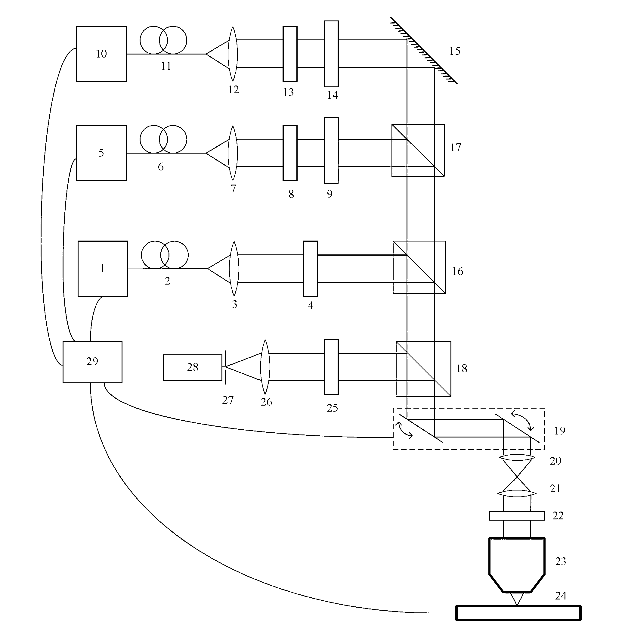
[0081] Such as figure 1 As shown, a three-dimensional super-resolution microscopy device based on intensity difference includes: a first laser 1, a first single-mode fiber 2, a first collimator lens 3, a first polarizer 4, a second laser 5, a second Single-mode fiber 6, second collimator lens 7, second polarizer 8, first phase modulator 9, third laser 10, third single-mode fiber 11, third collimator lens 12, third polarizer 13, the second phase modulator 14, mirror 15, first beam splitter 16, second beam splitter 17, third beam splitter 18, scanning galvanometer system 19, scanning lens 20, field mirror 21, 1 / 4 wave plate 22, microscope objective lens 23, nanometer displacement stage 24, bandpass filter 25, focusing lens 26, pinhole 27, detector 28, controller 29.

[0082] Wherein, the first single-...


PUM


Abstract

The invention discloses a intensity difference based three-dimensional super-resolution microscopic method, which includes the following steps of: 1) starting a confocal imaging mode, converting the light beam sent out from a first light source into first linearly polarized light; 2) projecting the first linearly polarized light onto a sample to be tested; 3) collecting the signal light sent by the sample to be tested, thus obtaining first signal light intensity I1; 4) switching to a negative confocal imaging mode, converting the light beams sent out from a second light source and a third light source into second linearly polarized light and third linearly polarized light respectively; 5) carrying out phase modulation on the second linearly polarized light and the third linearly polarized light, and then converting them into a first modulated light beam and a second modulated light beam respectively; 6) projecting the first modulated light beam and the second modulated light beam onto the sample to be tested; 7) collecting the signal light sent by the sample to be tested, thus obtaining second signal light intensity I2; and 8) calculating effective signal light intensity I so as to obtain a super-resolution image. The invention also discloses an intensity difference based three-dimensional super-resolution microscopic device.

Description

technical field [0001] The invention belongs to the field of optical microscopy, in particular to a three-dimensional super-resolution microscopy method and device based on intensity difference. Background technique [0002] Due to the influence of the optical diffraction limit, the resolution of conventional optical microscopes is generally difficult to be less than 200nm, so it is impossible to observe nanoscale samples, which limits its application in nanotechnology and biotechnology. [0003] In recent years, in order to break through the limitations of the optical diffraction limit, researchers have proposed a variety of super-resolution microscopy methods, including: [0004] Stimulated Emission Depletion Microscopy (STED: Stimulated Emission Depletion Microscopy): Utilizes the nonlinear relationship between fluorescence saturation and excited-state fluorescence stimulated loss, and by limiting the area of ​​stimulated radiation attenuation, the size of the fluorescent...

Claims


Application Information

Patent Timeline
Patent Type & Authority Applications(China)
IPC IPC(8): G01N21/64G01N21/21
Inventor 匡翠方李帅郝翔顾兆泰刘旭
Owner ZHEJIANG UNIV
Learn More